22 CA300 O300EN1
INSTRUCTIONS FOR LIFTING
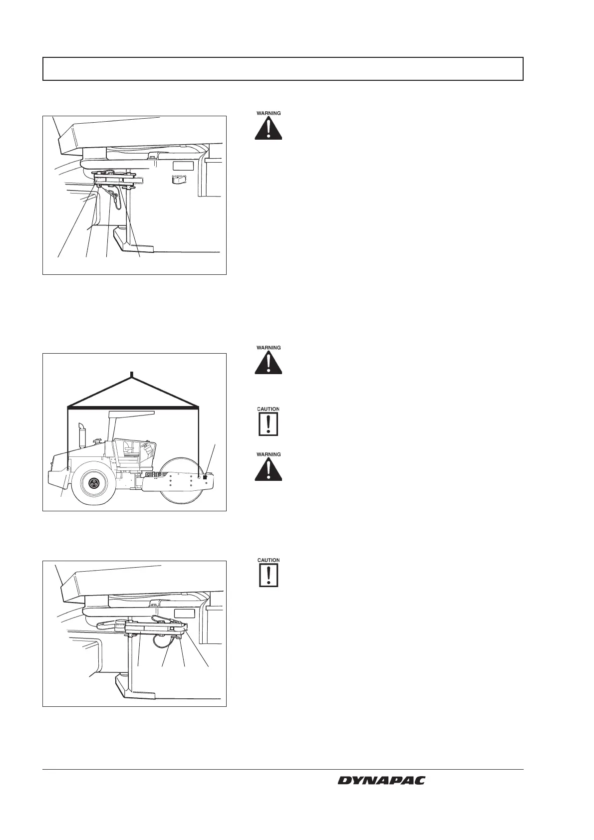
Fig. 25 Articulation in open mode
1. Locking arm
2. Locking cotter
3. Locking stud
4. Locking lug
Locking the articulated joint
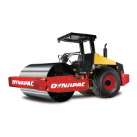
Lifting the roller
Releasing the articulated joint
Articulation must be locked to prevent
inadvertent turning before lifting the roller.
Turn the steering wheel so that the machine is set to
drive straight forward. Push in the reserve/parking
brake knob.
Pull out the lowermost locking cotter (2) fitted with a
wire, pull up locking stud (3) fitted with a wire.
Fold out the locking arm (1) and secure it to the upper
locking lug (4) on rear machine frame.
Fit the locking stud (3) in the holes through the locking
arm (1) and locking lug (4) and secure the stud in
position with the locking cotter (2).
Fig. 24 Roller prepared for lifting
1. Lifting plate
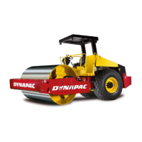
Fig. 23 Articulation in interlocked mode
1. Locking arm
2. Locking cotter
3. Locking stud
4. Locking lug
Remember to restore the articulation interlock
to its open mode before driving again.
Fold back the locking arm (1) and secure it in the
locking lug (4) with the locking stud (3). Insert the
lowermost locking cotter (2) fitted with a wire, to secure
the locking stud (3). The locking lug (4) is located on
the tractor frame.
1
1
32
4
432
The gross weight of the machine is noted
on the lifting plate (1). See also technical
specifications in the maintenance instruc-
tions.
Lifting gear, such as chains, steel wires,
straps, and lifting hooks must be dimensioned
in conformance with current regulations.
Keep well clear of the lifted machine! Make
sure that lifting hooks are securely anchored.
1
1
Weight: See lifting plate on the roller.