10
WLT6000-1EN1
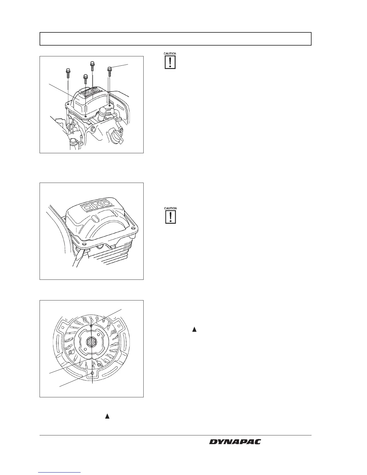
2. To remove the head cover, insert a screw driver or
equivalent tool into the recess in the position of
cylinder shown. Remove the head cover slowly.
Do not remove the head cover with force,
because that can deform the head cover.
Replace the head cover if it is deformed.
3. Remove the recoil starter.
VALVE CLEARANCE LT 6000
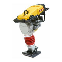
Fig. 14 Valve.
1. Flange bolts x4
2. Cylinder head cover
Valve clearance inspection and adjustment
must be performed with the engine cold.
1. Loosen the four 6 x14 mm flange bolts(1).
Fig. 15 Cylinder head cover.
1
2
Fig. 16 Mark
1. Cutout
2. Alignment mark
3. Lower bolt hole
4. Set the piston at top dead center of the compression
stroke (both valves fully closed). Top dead center of
the compression stroke is the the point there where
the cutout (1) in the starter pully (i.e. opposite side
from the
mark (2) on the flywheel) is in alignment
with the lower bolt hole (3) of the fan cover.
If the exhaust is opens when the cutout in the starter
pulley is aligned with the lower bolt hole on the fan
cover, turn the flywheel one turn and align the
marks.
The top dead center of the compression stroke is in
the position where the head cover mating surface
aligns with the cam pulley alignment marks.
2
1
3
W000016A
W000017A
W000018A