17
WLT6000-1EN1
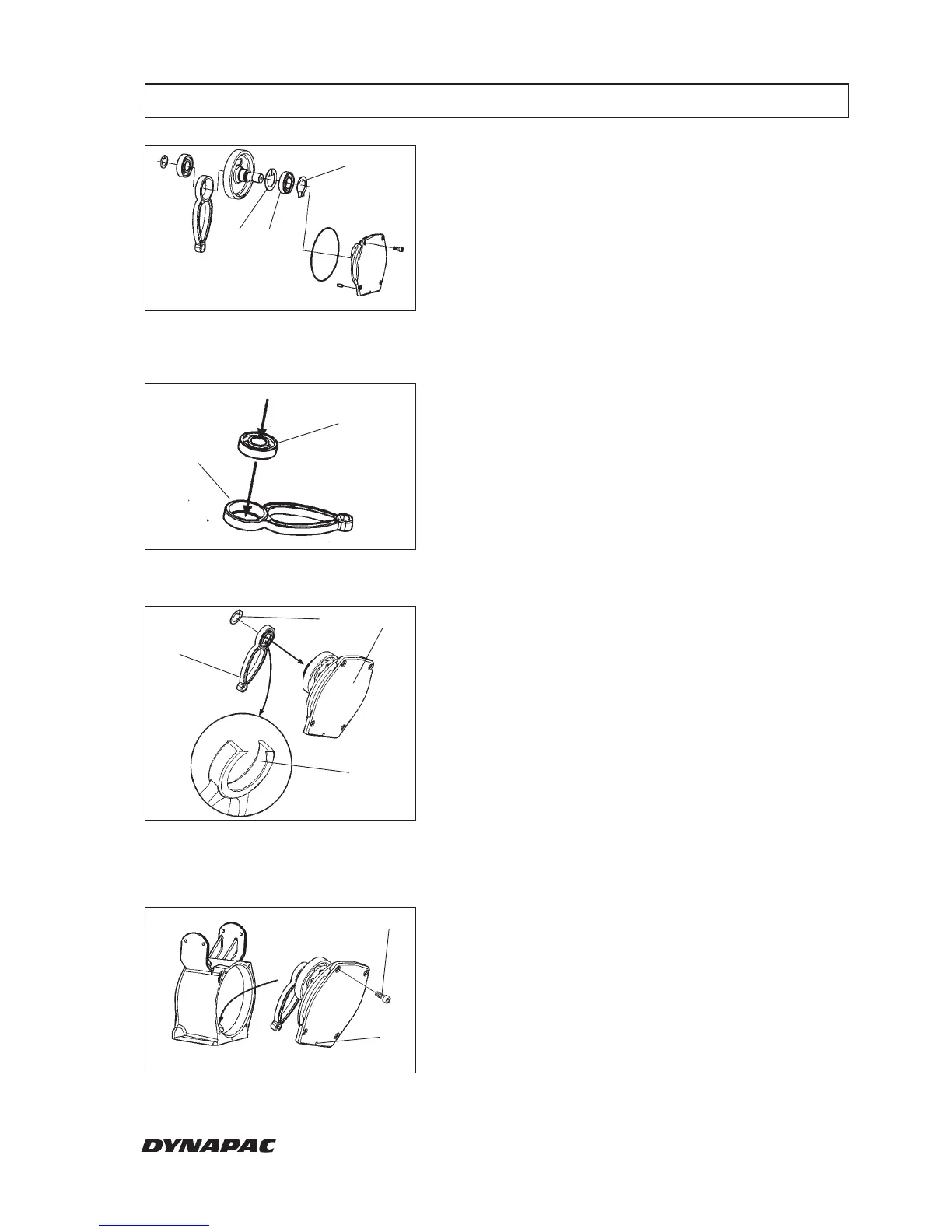
REASSEMBLY THE CRANK CASE
Fig. 32 Crank shaft
1. Ball bering
2. Snap ring
3. Snap ring
1. Before reassemblying the crank case, clean
parts and surfaces.
Check the O-ring so it is in good conditions.
Before reassembly the bearing (1) don't forget
the snap ring (2)
Mount the bearing (1) and the snap ring (3)
Mount the snap ring (2) in the cover unit
2. Clean parts and mount the ball bering in the
crank shaft.
Fig. 33 Ball bearing
4. Ball bearing
5. Crank shaft
Fig. 34 Crank shaft
6. Crank shaft
7. Snap ring
8. Flange
9. Cover
3. Mount the crankshaft (6) and lock it with the snap
ring (7).
Important:
Mount the crankshaft with the flange against the
cover (9).
4. Mount the O-ring between cover unit and
crank case, torque screws (10) dry crosswise
to 45 Nm.
Don't forget the pin (11)
Fig. 35 Crank shaft
10. Scews x4
11. Pin
3
1
2
4
5
10
11
W000043A
W000046A
W000048A
7
9
6
8
W000047A