15
WLT6000-1EN1
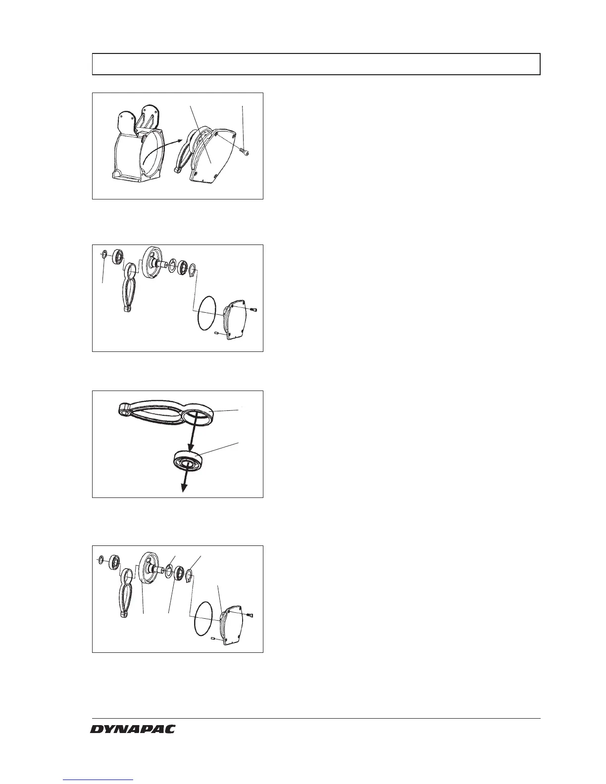
DISASSEMBLY THE CRANK CASE
Fig. 27 Crankcase
1. Screw x4
2. Cover
Fig. 28 Crankcase
3. Snap ring
Fig. 29 Crankshaft
4. Ball bearing
5. Crankshaft
Fig. 30 Crankshaft
6. Gear wheel
7. Needle bearing
8. Snap ring
9. Ball bearing
10. Snap ring
1. Remove the crank case. (see previous side).
2. Unscrew the four screws crosswise (1) and remove
the cover unit (2).
2
1
3. Remove the snap ring (3) and remove the crank
shaft. Use a puller to remove the crankshaft from
the gear.
3
5
4
4. Remove the ball bearing (4) from the crank shaft (5).
8
7
9
10
6
5. Loosen snap ring (10)
6. Remove gear wheel (6), Use two M8 screws to
press out gear wheel from the bearing (7). This
needle bearing is mounted in the cover .
Remove snap ring (8) and pull of bearing (9)
W000042A
W000043A
W000044A
W000043A