18
WLT6000-1EN1
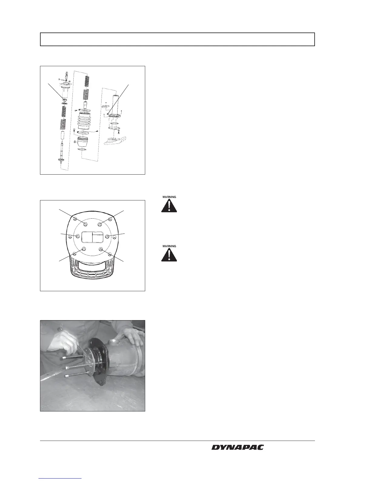
4. Remove three screws (1) and replace this with three
fully treaded screws M8x150 mm with washer and
nuts and retighten.
Spring load. DO NOT remove the other
three screws at this moment.
5. Loosen the remaining three screws (2) M8x20 mm
SPRING UNIT
Fig. 36 Tamper leg.
1. Rod piston head
2. oil plug
Dismantling the spring assembly
1. Dismantling is the same as change of bellows.
2. Remove rod piston head (1).Use an open end
spanner (size 23) to hold the piston shaft
3. Drain the oil from spring cylinder assy before turning
it upside down.
Fig. 37 Screws bottom side tamper leg.
1. Screws M8x150 mm
2. Screws M8X20 mm
1
2
2
2
2
1
1
1
Fig. 38 Screws bottom side tamper leg.
1. Screws M8x150 mm
2. Screws M8X20 mm
The spring assembly is pre-tensioned, ie, it
is pressed together 125 mm.
6. Then loosen the three "long" screws alternately until
the spring load is released.
7. Refil oil in the leg. (sight plug).
W000035A
W000032A
W000033A