11
WLT6000-1EN1
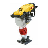
Fig. 17 Valve adjustment
1. Feeler gauge
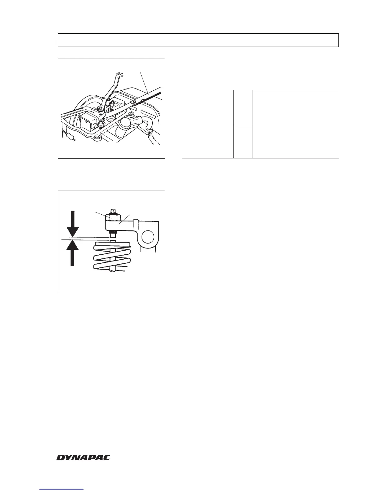
Fig. 18 Valve adjustment
1. Adjusting screw.
2. Lock nut.
6. If adjustment is necessary, proceed as follows.
1. Hold the valve adjusting screw (1), and loosen the
lock nut (2).
2. Turn the adjusting screw to obtain the specified
intake and exhaust valve clearance.
3. Hold the valve adjusting screw, and tighten the
lock nut.
4. Recheck valve clearance after tightening the lock
nut.
7. Install the head cover and recoil starter.
1
1
2
VALVE CLEARANCE LT 6000
5. Insert the feeler gauge (1) between the valve
adjusting screw and the valve and measure the
valve clearence.
In 0,15 ± 0,02 mm
(0,006 ± 0,001 in)
Standard
valve
clearance
Ex 0,20 ± 0,02 mm
(0,008 ± 0,001 in)
W000019A
W000020A