12
WLT6000-1EN1
Valve clearance inspection and adjustment
must be performed with the engine cold.
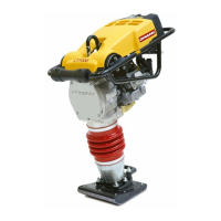
1. Remove the four cylinder bolts, cylinder head cover
and gasket.
VALVE CLEARANCE LT 7000
1
23
Fig. 19 Valve
1. Bolts
2. Cylinder head cover
3. Gasket
Fig. 21 Valve adjustment
1. Feeler gauge
1
Fig. 22 Valve adjustment
1. Rocker arm pivot
2. Rocker arm pivot lock nut
2
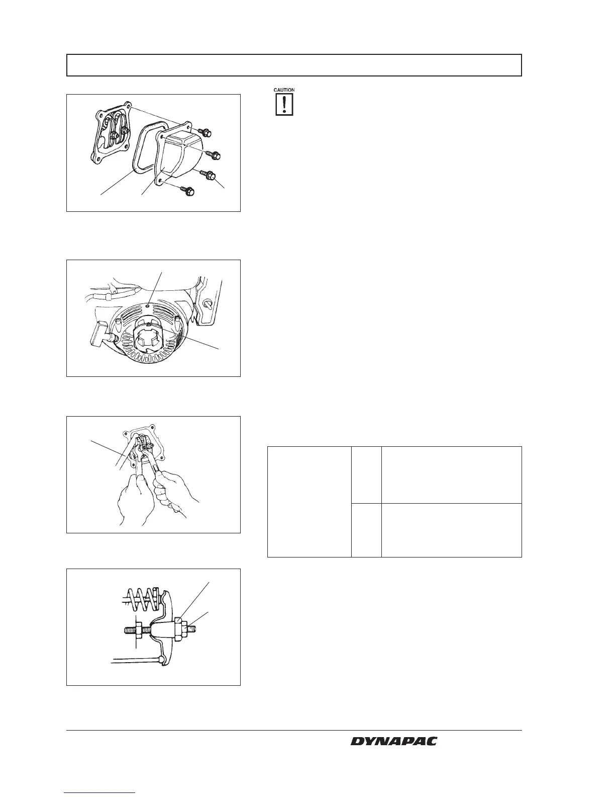
Fig. 20 Mark
1. Triangular mark
2. Top hole
2
1
1
2. Set the piston at top dead center of the compression
stroke (both valves fully closed). The triangular
mark on the starter pulley will align with the top hole
on the fan cover when the piston is at top dead
center of the compression or exhaust stroke.
In 0,15 ± 0,02 mm
(0,006 ± 0,001 in)
Standard
valve
clearance
Ex 0,20 ± 0,02 mm
(0,008 ± 0,001 in)
3. Insert a feeler gauge between the rocker arm and
valve to measure valve clearance.
4. IF adjustment is necessary, proceed as follows:
1. Hold the rocker arm pivot and loosen the rocker
arm pivot lock nut.
2. Turn the rocker arm pivot to obtain the specified
clearance.
3. Retighten the rocker arm pivot lock nut while
holding the rocker arm pivot.
4. Recheck valve clearance after tightening the
rocker arm pivot lock nut.
W000021A
W000022A
W000023A
W000024A