Installation & Start Up
DYN-LOC IV AND CUSTOMER-SUPPLIED CONTROL START-UP
When the PAU is powered up in the Automatic Reset Mode, the
dynamometer could power up in the same state it was in when power was
turned off.
1. Validate the conguration listed on the cover of the manual and exterior of the unit
are identical and appropriate for your application. If these values do not match or
are not appropriate for your application, please contact Dyne Systems.
2. Verify the integrity of power wiring (i.e. no shorts to ground, verify coil resistance,
etc).
3. Power up the Dyn-Loc IV (or customer control).
4. Apply power to the PAU. When power is applied a reset is not required.
The following faults are self-restoring:
• SCR OverTemp • Current OverCmd
• Coolant OverTemp • Spare Safeties
• Coolant P/F
The following faults require the power to be turned off and the fault corrected
before reapplying power:
• I Current Err
• Current Reversed
• No Field Current
5. The following will appear on the display for ~3 seconds:
Eddy-Current PAU
XX.X A max VX.X
XX.XA - The maximum current of the PAU (15, 30, 50, 100)
VX.X - The version of rmware
6. The following will then appear on the display:
PAU:Ok Off
0% 0.0A
PAU:Ok - Signies everything is okay, or else the word Fault is displayed
(Refer to Rack Mount Troubleshooting Guide on page 26).
Off - PAU is not enabled
% - Percentage of command voltage 0-10VDC or 0-20mA
A - Amount of current being applied to coil
If Fault is displayed, power down the Dyn-Loc IV (or customer control) and PAU,
correct the fault, and then go back to Step 3.
7. Perform the Max Current adjustment if this is the rst time use. (See Appendix A,
p.32 for setting Max Current.)
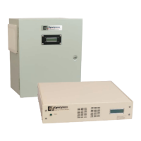
8. Your DS820F PAU is ready for use.
22 Dyne Systems • DS820F PAU
DPD-001-04B • © Copyright Dyne Systems, Inc.