Application Specic Functionality
Additional Safeties
In addition to the two H
2
O safeties (Coolant Temp and Coolant P/F) there are three inputs
available for custom safeties or faults. TB3-1 thru TB3-6 provide connections for up to three
dry contacts (closed = OK to run). Opening of these contacts will generate a fault. The LCD
display will show “GP Input Fault 1, 2 or 3”. This message can be customized at the factory if
desired. The DS820F ships with jumpers in these inputs.
Note: Reference Table 7.1 (next page) for all jumper denitions.
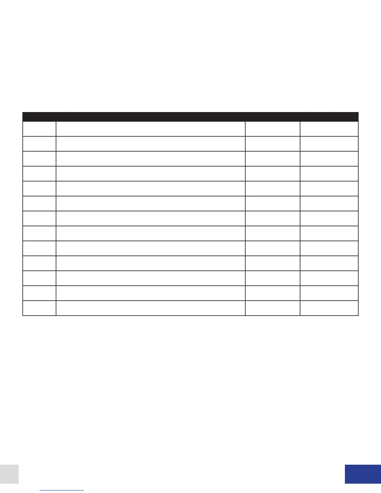
DS820F Control Board Jumper Definitions
Jumper Description Default Positiion Installed
JP1 OUT = Voltage input (0-10 VDC) IN = Current Input (0-20mA) OUT NO (Hanging)
JP2 Low Inductance Coil Jumper IN = Low Inductance Coil OUT NO (Hanging)
JP3 External Current Command Source = Rack Mount OUT NO (Hanging)
JP4 External Current Command Source = Wall Mount IN YES
JP5 External Armature Feedback from TB9 OUT NO (Hanging)
JP6 IL5 / TB12 Dyne On Select POS A = IL5, POS B = TB12 (Isolated) POS A YES
JP7 Low “Max” Current Jumper OUT NO (Hanging)
JP8 Connects power commons Hardwired N/A
JP9 Connects power commons Hardwired N/A
JP10 Connects power commons Hardwired N/A
JP12 Input Voltage Offset IN = Allows P7 to Zero Input OUT NO (Hanging)
JP13 Scaled Analog Output Jumper (directs to Pin 8 of CON1) OUT NO (Hanging)
JP14 50 / 60Hz Select POS A = 60Hz, POS B = 50Hz POS A YES
Table 7.1
Dyne Systems • DS820F PAU
DPD-001-04B • © Copyright Dyne Systems, Inc.
25