DYNE SYSTEMS, INC. ~ MIDWEST & DYNAMATIC DYNAMOMETERS ~ DYNE SYSTEMS, INC. ~ MIDWEST & DYNAMATIC DYNAMOMETERS ~ DYNE SYSTEMS,
INC. ~ MIDWEST & DYNAMATIC DYNAMOMETERS ~ DYNE SYSTEMS, INC. ~ MIDWEST & DYNAMATIC DYNAMOMETERS ~ DYNE SYSTEMS, INC. ~ MIDWEST &
DYNAMATIC DYNAMOMETERS ~ DYNE SYSTEMS, INC. ~ MIDWEST & DYNAMATIC DYNAMOMETERS ~ DYNE SYSTEMS, INC. ~ MIDWEST & DYNAMATIC DYNA-
MOMETERS ~ DYNE SYSTEMS, INC. ~ MIDWEST & DYNAMATIC DYNAMOMETERS ~ DYNE SYSTEMS, INC. ~ MIDWEST & DYNAMATIC DYNAMOMETERS ~ DYNE
SYSTEMS, INC. ~ MIDWEST & DYNAMATIC DYNAMOMETERS ~ DYNE SYSTEMS, INC. ~ MIDWEST & DYNAMATIC DYNAMOMETERS ~ DYNE SYSTEMS, INC. ~ MID-
WEST & DYNAMATIC DYNAMOMETERS ~ DYNE SYSTEMS, INC. ~ MIDWEST & DYNAMATIC DYNAMOMETERS ~ DYNE SYSTEMS, INC. ~ MIDWEST & DYNAMATIC
DYNAMOMETERS ~ DYNE SYSTEMS, INC. ~ MIDWEST & DYNAMATIC DYNAMOMETERS ~ DYNE SYSTEMS, INC. ~ MIDWEST & DYNAMATIC DYNAMOMETERS
~ DYNE SYSTEMS, INC. ~ MIDWEST & DYNAMATIC DYNAMOMETERS ~ DYNE SYSTEMS, INC. ~ MIDWEST & DYNAMATIC DYNAMOMETERS ~ DYNE SYSTEMS,
INC. ~ MIDWEST & DYNAMATIC DYNAMOMETERS ~ DYNE SYSTEMS, INC. ~ MIDWEST & DYNAMATIC DYNAMOMETERS ~ DYNE SYSTEMS, INC. ~ MIDWEST &
DYNAMATIC DYNAMOMETERS ~ DYNE SYSTEMS, INC. ~ MIDWEST & DYNAMATIC DYNAMOMETERS ~ DYNE SYSTEMS, INC. ~ MIDWEST & DYNAMATIC DYNA-
MOMETERS ~ DYNE SYSTEMS, INC. ~ MIDWEST & DYNAMATIC DYNAMOMETERS ~ DYNE SYSTEMS, INC. ~ MIDWEST & DYNAMATIC DYNAMOMETERS ~ DYNE
SYSTEMS, INC. ~ MIDWEST & DYNAMATIC DYNAMOMETERS ~ DYNE SYSTEMS, INC. ~ MIDWEST & DYNAMATIC DYNAMOMETERS ~ DYNE SYSTEMS, INC. ~ MID-
WEST & DYNAMATIC DYNAMOMETERS ~ DYNE SYSTEMS, INC. ~ MIDWEST & DYNAMATIC DYNAMOMETERS ~ DYNE SYSTEMS, INC. ~ MIDWEST & DYNAMATIC
DYNAMOMETERS ~ DYNE SYSTEMS, INC. ~ MIDWEST & DYNAMATIC DYNAMOMETERS ~ DYNE SYSTEMS, INC. ~ MIDWEST & DYNAMATIC DYNAMOMETERS ~
DYNE SYSTEMS, INC. ~ MIDWEST & DYNAMATIC DYNAMOMETERS ~ DYNE SYSTEMS, INC. ~ MIDWEST & DYNAMATIC DYNAMOMETERS ~ DYNE SYSTEMS, INC.
~ MIDWEST & DYNAMATIC DYNAMOMETERS ~ DYNE SYSTEMS, INC. ~ MIDWEST & DYNAMATIC DYNAMOMETERS ~ DYNE SYSTEMS, INC. ~ MIDWEST &
DYNAMATIC DYNAMOMETERS ~ DYNE SYSTEMS, INC. ~ MIDWEST & DYNAMATIC DYNAMOMETERS ~ DYNE SYSTEMS, INC. ~ MIDWEST & DYNAMATIC DYNA-
MOMETERS ~ DYNE SYSTEMS, INC. ~ MIDWEST & DYNAMATIC DYNAMOMETERS ~ DYNE SYSTEMS, INC. ~ MIDWEST & DYNAMATIC DYNAMOMETERS ~ DYNE
SYSTEMS, INC. ~ MIDWEST & DYNAMATIC DYNAMOMETERS ~ DYNE SYSTEMS, INC. ~ MIDWEST & DYNAMATIC DYNAMOMETERS ~ DYNE SYSTEMS, INC. ~ MID-
WEST & DYNAMATIC DYNAMOMETERS ~ DYNE SYSTEMS, INC. ~ MIDWEST & DYNAMATIC DYNAMOMETERS ~ DYNE SYSTEMS, INC. ~ MIDWEST & DYNAMATIC
DYNAMOMETERS ~ DYNE SYSTEMS, INC. ~ MIDWEST & DYNAMATIC DYNAMOMETERS ~ DYNE SYSTEMS, INC. ~ MIDWEST & DYNAMATIC DYNAMOMETERS ~
DYNE SYSTEMS, INC. ~ MIDWEST & DYNAMATIC DYNAMOMETERS ~ DYNE SYSTEMS, INC. ~ MIDWEST & DYNAMATIC DYNAMOMETERS ~ DYNE SYSTEMS, INC.
~ MIDWEST & DYNAMATIC DYNAMOMETERS ~
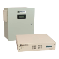
DS820F
Power Amplier Unit
www.dynesystems.com
Job # ____________________
Model # __________________
Serial # __________________
Conguration (amps) _______
Controller Conguration
Inter-Loc V Control
Dyn-Loc IV Control
Customer-Supplied Control, 0-10 VDC
DPD-001-04B
USER MANUAL