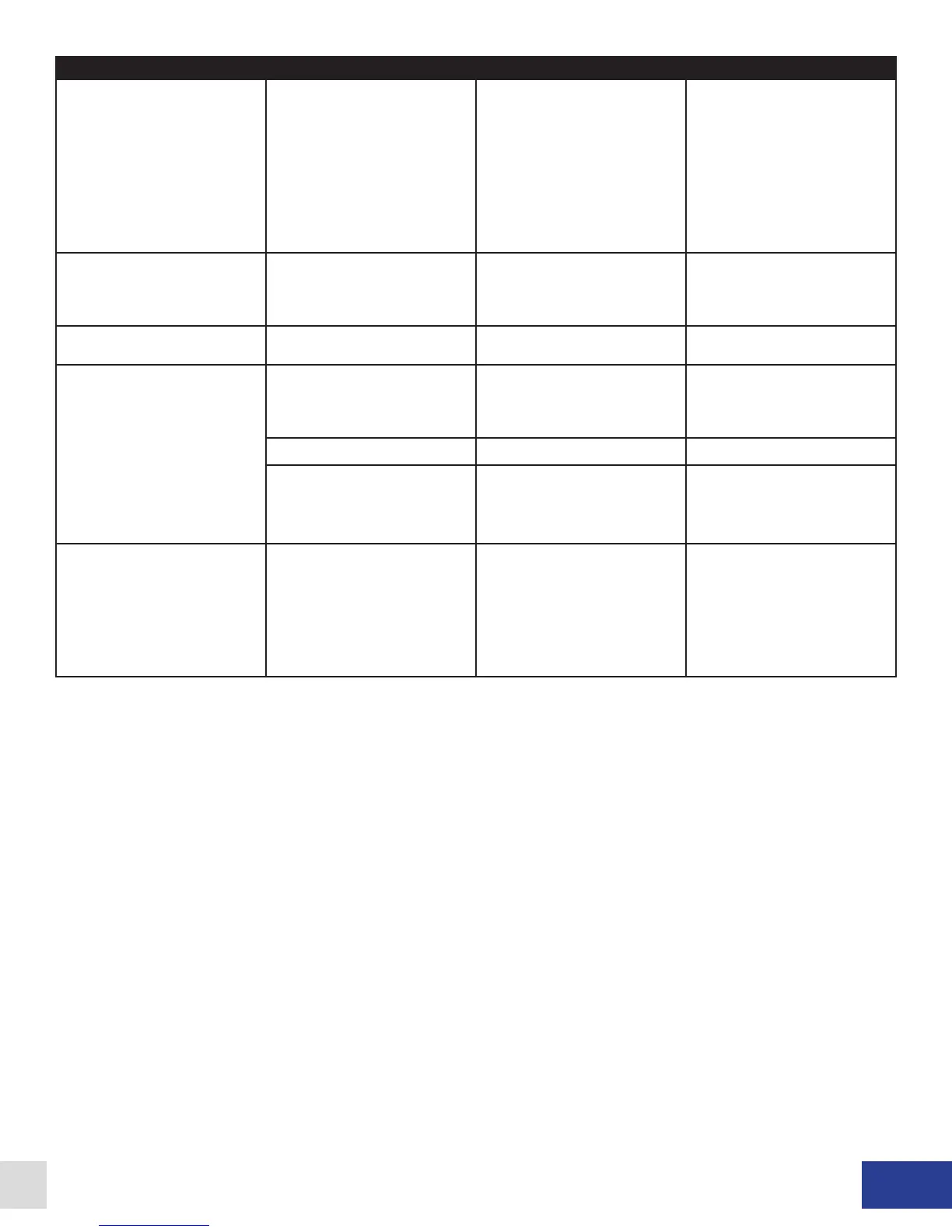
Faults/Troubleshooting
Fault/Problem Cause Wall Mount Solution Rack Mount Solution
Coolant P/F fault showing in
LCD display.
The dynamometer cooling
system pressure (or ow) has
dropped below the setpoint of
the coolant pressure (or ow)
switch (closed = safe to run).
Verify the operation of the
various components making
up the dyno cooling system.
Check functionality of coolant
pressure (or ow) switch and
its connections to TB4-1 and
TB4-2. If a pressure (or ow)
switch is not installed, a jumper
should be installed across
these terminals.
Verify the operation of the
various components making
up the dyno cooling system.
Check functionality of coolant
pressure (or ow) switch and
its connections to AUX-3 and
AUX-8. If a pressure (or ow)
switch is not installed, a jumper
should be installed across
these terminals.
I Feedback Err fault showing in
the LCD display.
The sensed current ow is
different than the system
expected.
If using a low inductance coil,
try installing jumper JP2.
Contact Dyne Systems.
If using a low inductance coil,
try installing jumper JP2.
Contact Dyne Systems.
Current Reversed fault showing
in LCD display.
Current transducer wiring is
incorrect.
Contact Dyne Systems Contact Dyne Systems
No Field Current fault showing
in LCD display.
Defective eld coil, or wiring to
the eld coil.
Verify eld coil integrity and its
connections to the PAU at
TB6-3 and TB6-4.
Verify eld coil integrity and
its connections to the PAU at
appropriate connector
(see Fig. 5.6 or Fig. 5.7).
Main PAU fuses open. Not Applicable Check fuses (FU1, FU2).
Defective eld power
transformer
Verify operation of eld power
transformer and its connections
to TB6-5, TB6-6, TB6-7 and
TB6-8.
Verify operation of eld power
transformer and its connections
at appropriate connector
(see 5.6 or Fig. 5.7).
Current OverCmd fault showing
in LCD display.
The applied current command
signal has exceeded 110%.
The nominal current
reference range is 0 to 100%.
Commanded currents of 101%
are allowed indenitely, 102%
- 109% for approximately 10
seconds, 110% (or greater) are
not allowed.
The nominal current
reference range is 0 to 100%.
Commanded currents of 101%
are allowed indenitely, 102%
- 109% for approximately 10
seconds, 110% (or greater) are
not allowed.
Table 8.1 - Wall and Rack Mount Troubleshooting Guide
Dyne Systems • DS820F PAU
DPD-001-04B • © Copyright Dyne Systems, Inc.
27