Faults/Troubleshooting
SECTION 8: FAULTS /TROUBLESHOOTING
Only qualied licensed electricians should open the PAU enclosure.
NOTE: The Coolant Pressure/Flow safety input has a delay of ~5 seconds in the Reset Required
Mode and is instant in the Automatic Reset Mode.
NOTE: The Coolant Temperature Safety input, along with the three Spare Safety inputs are
instant in both Reset Modes.
NOTE: The main circuit board for the PAU has two LEDs (see Figure A.1, page 33 -
DS820F Main Circuit Board). The LED toward the center of the board will pulse
once each second. If the LED is not blinking the circuit board is defective or it is
not getting power.
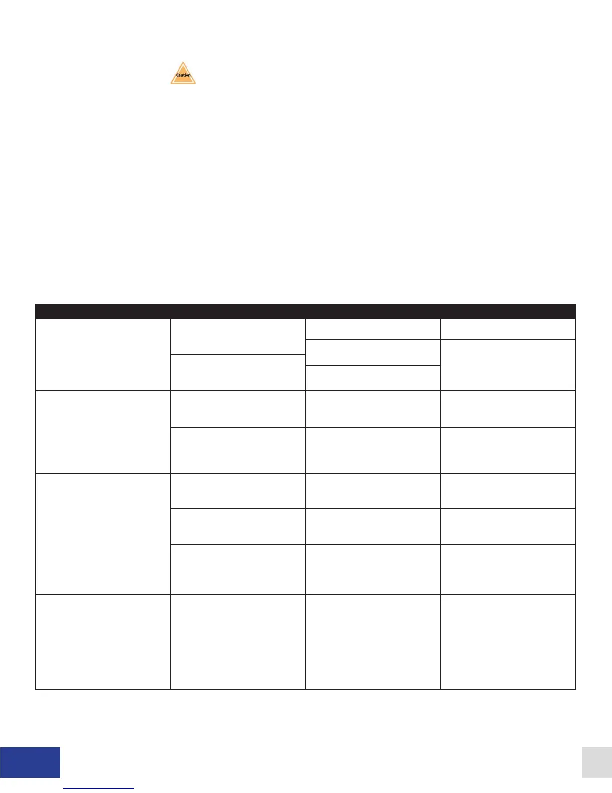
Please refer to Table 8.1, Troubleshooting Guide (below).
Wall Mount and Rack Mount Troubleshooting Guide
Fault/Problem Cause Wall Mount Solution Rack Mount Solution
No indication of Power. (LCD
display blank, no red LED
activity on DS820F logic board,
fan not running).
No power from mains. Verify integrity of Facility Mains Verify integrity of Facility Mains
Check PAU main fuses FC1,
FC2
Check fuse FB1-2 (internal)
Blown fuses.
Check PAU Control Transformer
fuses (FU1, FU2, FU3).
No output current from PAU. PAU not enabled. Ensure that there is an enable
signal (+24 VDC) at TB1-5.
Ensure that there is an enable
signal (+24 VDC) at Dyno
Control pin 3.
No current command signal. Check that a 0-10 VDC or
0-20mA reference is being
applied between TB1-2 (input)
and TB1-3 (common).
Check that a 0-10 VDC or
0-20mA reference is being
applied between Dyno Control
pins 1 (input) and 14 (common)
SCR OverTemp fault showing in
LCD display.
The SCR heat sink is too hot. Allow time for the heat sink to
cool down.
Allow time for the heat sink to
cool down.
Cooling fan not running. Verify operation of cooling fan
and its connections at TB6-1
and TB6-2.
Verify operation of cooling fan.
Check fan fuse FB1-1 (internal).
The heat sink temperature
switch (NC) is defective or
disconnected.
Verify the operation of the
temperature switch mounted
on the heat sink and its
connections.
Verify the operation of the
temperature switch mounted
on the heat sink and its
connections.
Coolant OverTemp fault
showing in LCD display.
The dynamometer cooling
system temperature has
exceeded the setpoint of the
coolant temperature switch
(closed = safe to run).
Allow system to cool down.
Verify the integrity of the
coolant temperature switch and
its connections to TB4-3 and
TB4-4. If a temperature switch
is not installed, a jumper should
be installed across these
terminals.
Allow system to cool down.
Verify the integrity of the
coolant temperature switch and
its connections to AUX-4 and
AUX-9. If a temperature switch
is not installed, a jumper should
be installed across these
terminals.
26 Dyne Systems • DS820F PAU
DPD-001-04B • © Copyright Dyne Systems, Inc.