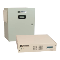
Appendix A - Max Current Adjustment
APPENDIX A: PAU MAX CURRENT ADJUSTMENT (CONTINUED)
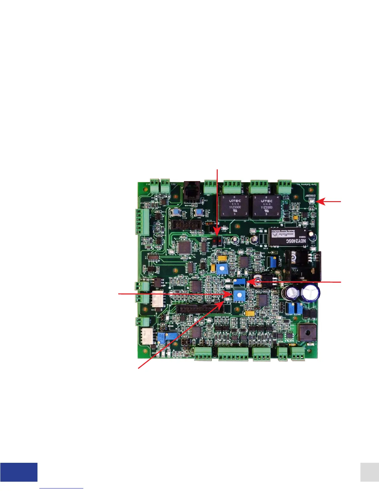
4. Power ON the PAU.
5. Enable the PAU and apply 100% command signal set at +10.0VDC or 20mA.
6. While enabled, adjust P3 (Max Current Setting) until the desired coil current is reached
(CCW lowers the coil current and CW increases the coil current). The new eld current
setting is displayed on the LCD display. Physically measure the coil current as a
precaution. Make sure the measured current closely matches the LCD display.
7. Disable the PAU.
8. Connect a DMM to TP20 (black lead) and TP6 (red lead). Adjust P4 until you measure
-0.050VDC (negative 50mV).
9. Max current setting is complete
Figure A.1 - DS820F Main Circuit Board
34 Dyne Systems • DS820F PAU
DPD-001-04B • © Copyright Dyne Systems, Inc.