B-3
POWER REQUIREMENTS AND INSTALLATION
North America, Japan, and Locations Using 60 Hz Power
Version 4 Above Ground Model 250i Motorcycle Dynamometer Installation Guide
TESTING FOR CORRECT VOLTAGES
You must test the receptacle for proper voltages before the dyno is connected to the
outlet.
If the voltage readings do not match the following table, DO NOT connect
the dyno. You must have a licensed electrician correct the power
connection. Connecting the dyno to the incorrect voltage can result in
damage to the dyno and will void the dyno warranty. Contact Dynojet with
any questions.
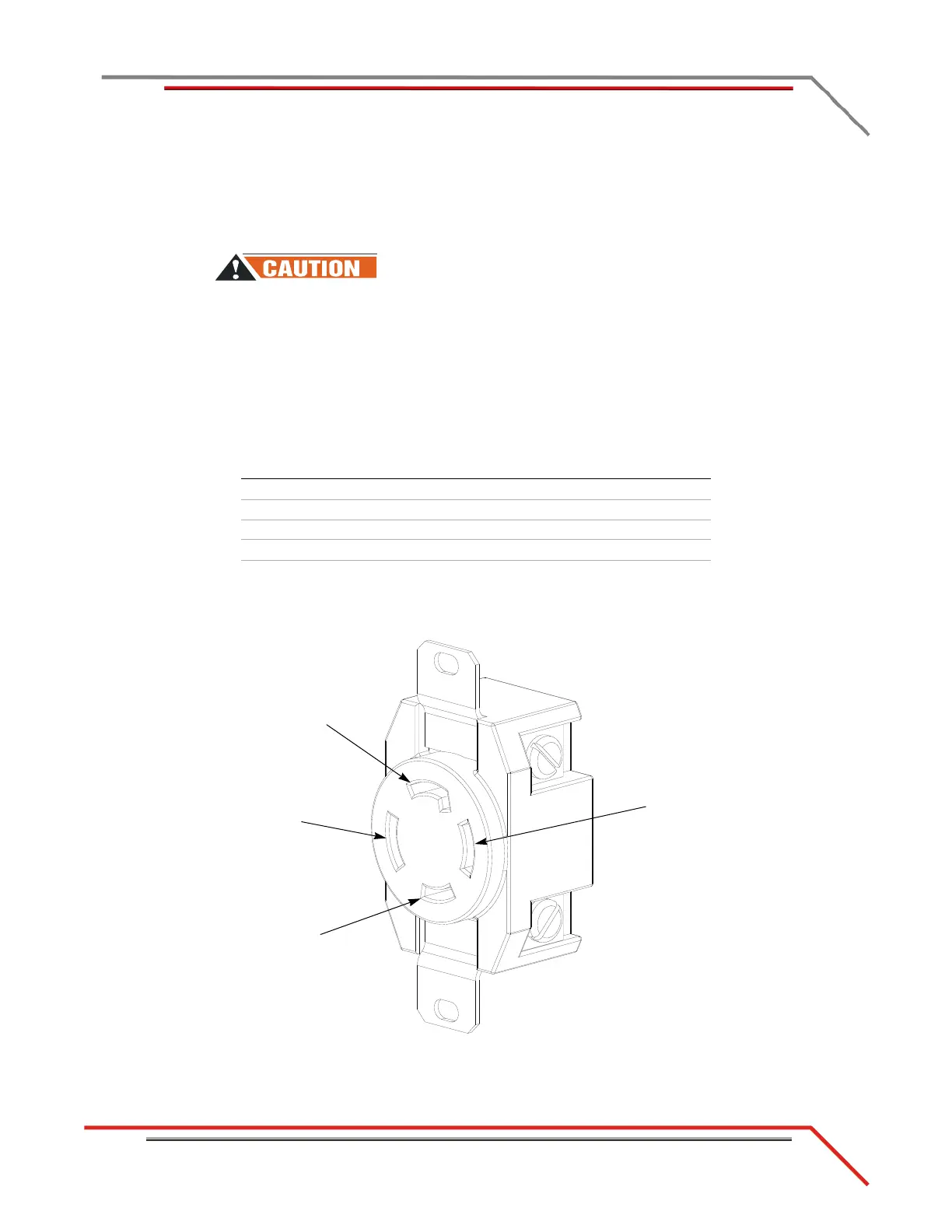
Using a voltmeter that is capable of measuring AC voltage, measure between the
points listed below and verify that the correct voltages are present.
Figure B-1: Dedicated Power Receptacle
probe 1 probe 2
desired voltage
measurement
2 4 216V to 260V*
1 4 108V to 130V
1 2 108V to 130V
3box<5V
*If using two of the three-phase lines of a 120/208 V 3 phase Y system,
then expect to see 187V to 225V.
 Loading...
