CHAPTER 3
Extended Carriage
Above Ground Model 250i Motorcycle Dynamometer Installation Guide
3-18
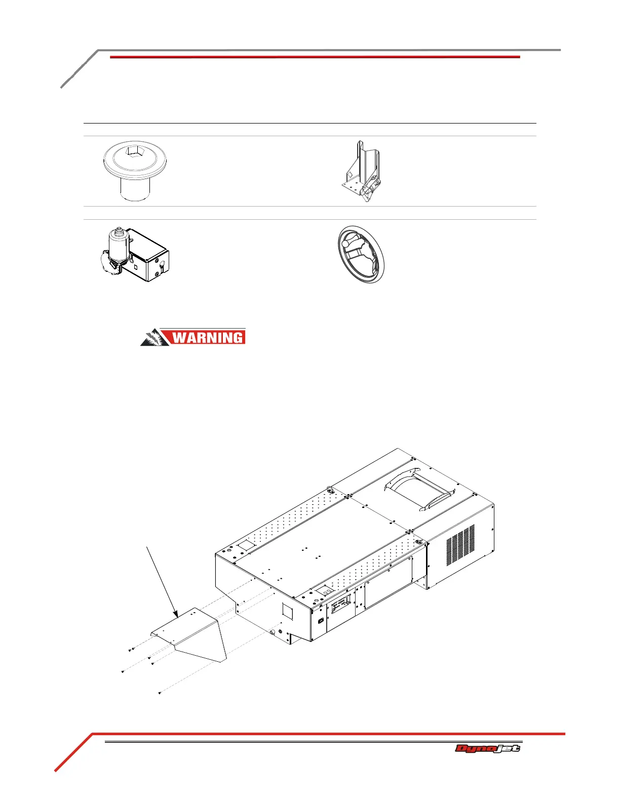
INSTALLING THE EXTENDED CARRIAGE SUPPORT BRACKET
To prevent possible injury, open the CPI door and set the main breaker to
the off position and unplug the dyno. Refer to “Main Dyno Power” on page
3-2 for breaker location.
1 Loosely attach the extended carriage support bracket to the front of the dyno
using six 3/8-16 x 1/2-inch button-head flange allen bolts.
2 Using a straight edge, line the top of the support bracket with the top of the dyno
chassis. Tighten all six screws.
Figure 3-19: Install the Extended Carriage Support Bracket
The following parts are included in the Tire Stop Assembly P/N 63310902:
bolt, 3/8-16 x 1/2", button-
head, flange, allen (4)
P/N 36580434
tire stop
P/N 63310902
The following parts are optional accessories:
power carriage assembly
P/N 82943001
hand wheel
P/N DM150-016-006
part description part description
extended carriage
support bracket
 Loading...
