Above Ground Model 250i Motorcycle Dynamometer Installation Guide
2-28
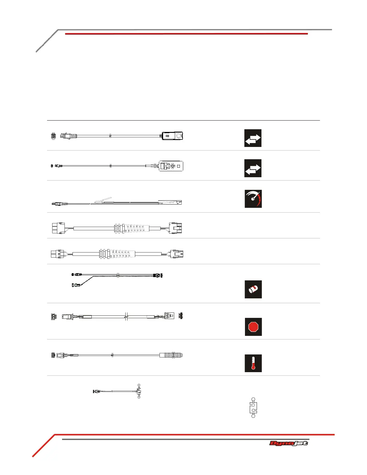
CABLE ROUTING
Use the following instructions to identify and route the cables. You will need to route
the cables before installing the covers.
IDENTIFYING THE CABLES
cable brief routing description
A - 66400011 remote atmos cable assembly connects to the DynoWare RT
B - 76100007 CAN pendant cable assembly connects to the DynoWare RT
C - 76950201 primary RPM pick up cable
- 76950203 secondary pick up cable
connects to the DynoWare RT
D - 76950307 wheel clamp cable assembly connects to the wheel clamp
E - 76950308 power carriage cable assembly connects to the power carriage
F - 76950548 speed pick up/brake cable connects the brake solenoid and speed pick up to the
DynoWare RT
G - 76950549 e-stop to CPI cable connects the DynoWare RT to P7 on the front of the
CPI panel
H - 76950569 IR temp sensor cable connects to the temp sensor cable to the eddy current
brake driver
I - 76950573 load cell cable connects the load cell to the eddy current brake
driver
*optional accessory
 Loading...
