2-25
DYNO INSTALLATION
Secure the Dyno and Brake Module to the Floor
Version 4 Above Ground Model 250i Motorcycle Dynamometer Installation Guide
SECURE THE DYNO AND BRAKE MODULE TO THE FLOOR
Dynojet recommends you anchor the eddy current brake, along with the dyno, to the
floor in your dyno room using concrete anchors. You will want to drill the holes and
secure the dyno before adding any accessories or replacing the covers on your dyno.
You will need the following parts:
• 36923100 Washer, 3/8", Hardened, Flat, Steel (6)
• 37513200 Anchor, Red Head, 3/8" (6)
•37518200 Red Head Anchor Installation Tool
• DM150-019-012 Bolt, 3/8-16 x 1", Hex (6)
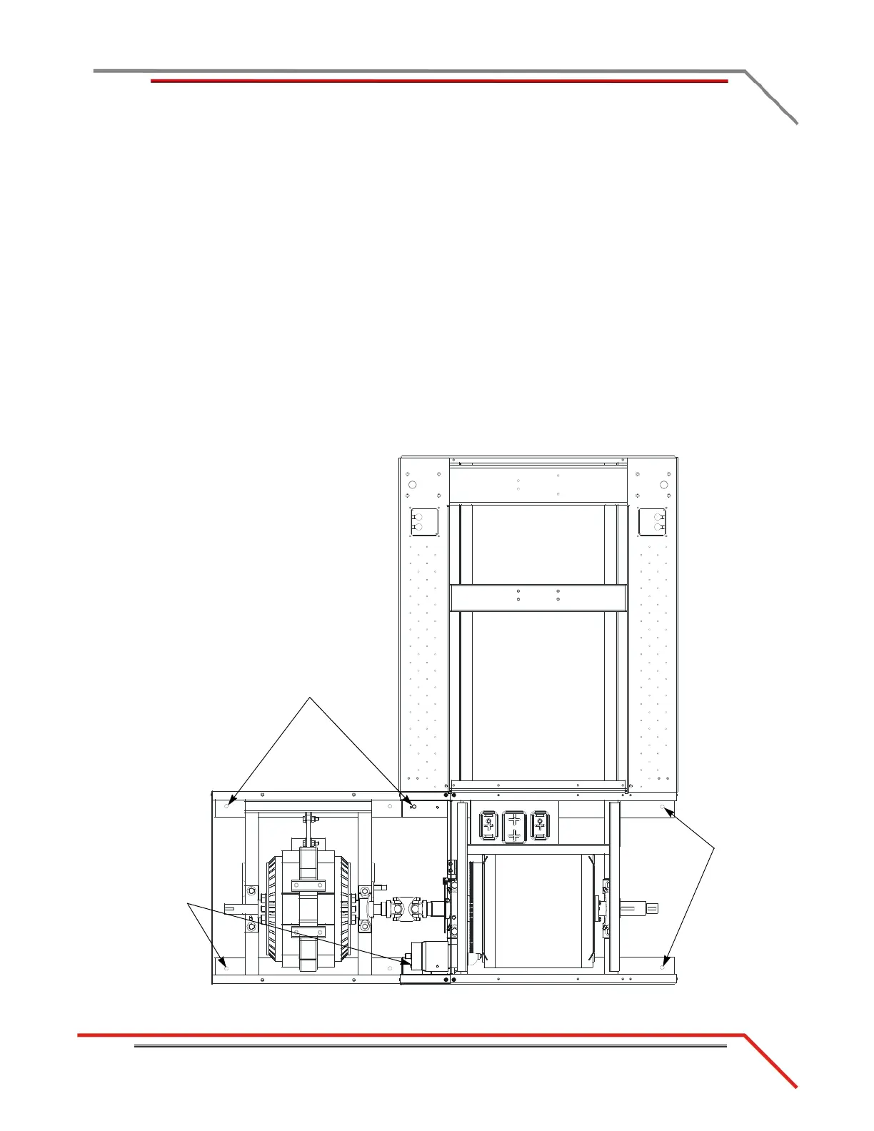
1 Using the dyno and brake module as a template, mark and drill each hole needed
to secure the dyno to the floor.
2 Install the Red Head anchors. Refer to Appendix A for installation instructions.
3 Secure the dyno and brake module to the floor using six 3/8-16 x 1-inch hex bolts
and six 3/8-inch flat washers.
Figure 2-23: Secure the Dyno and Brake Module to Floor
mark and drill
holes for red
head anchors
mark and drill
holes for red head
anchors
mark and drill
holes for red
head anchors
 Loading...
