APPENDIX C
Door Safety Switch
Above Ground Model 250i Motorcycle Dynamometer Installation Guide
C-6
DOOR SAFETY SWITCH
Safety requirements of your local country may require that a door safety switch is
installed. Be sure to follow the safety requirements specific to your country. The door
safety switch requires the air brake to work. This switch is located on the dyno room
door and is triggered when the pressure applied to it is released causing the air brake
to lock. This prevents the dyno from being used when the door is open.
For more information about the air brake, refer to “Air Brake” on page 3-3.
Components attached to and within the dynamometer operate with
potentially lethal voltages. To provide the greatest assurance of safety, the
AC power cord(s) must be disconnected from the power source before
servicing electrical components or wiring. Disconnect all power cords
before servicing electrical components for the greatest assurance of
safety.
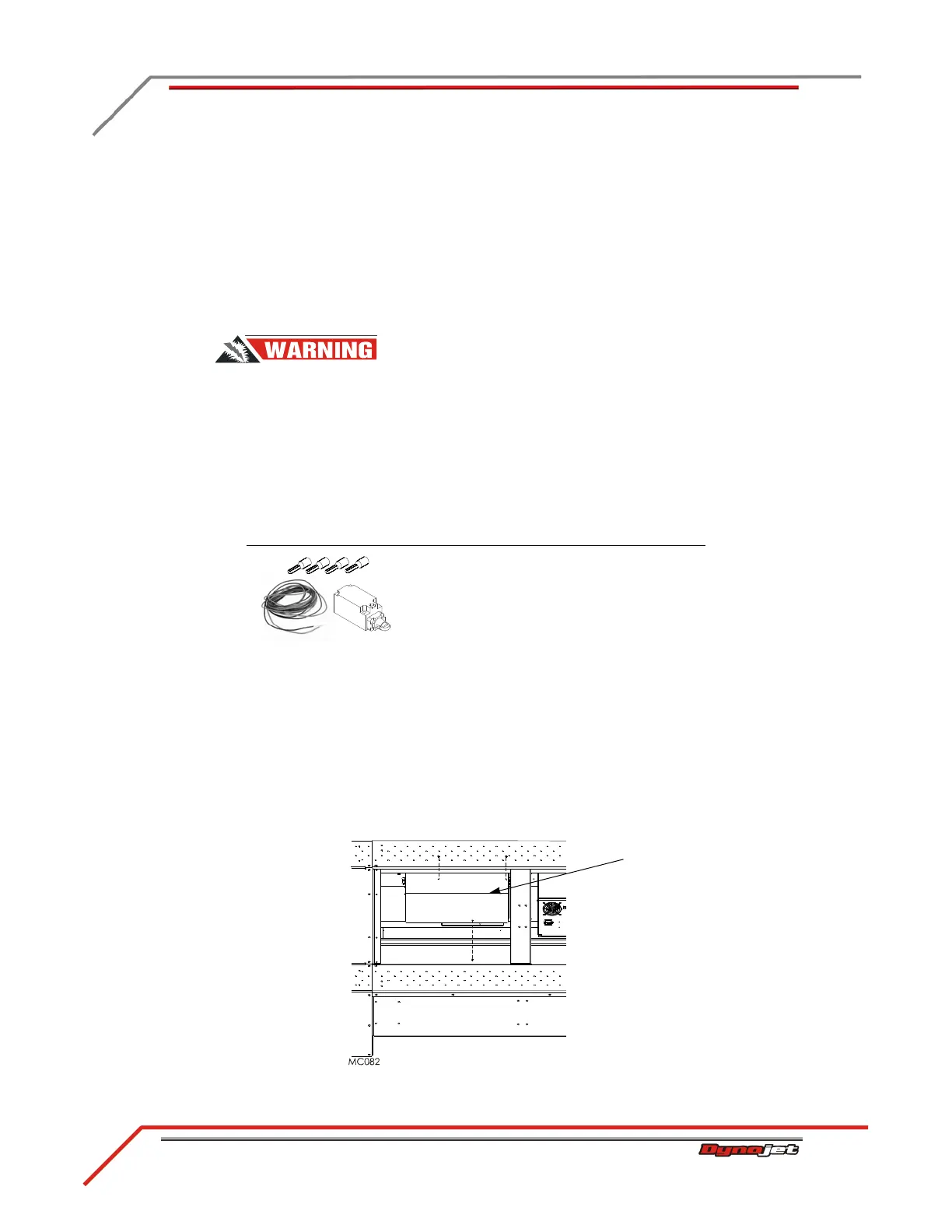
You will need the following part:
INSTALLING THE DOOR SAFETY SWITCH
1 Turn off the dyno and disconnect the AC power cord from its power source, refer
to “Main Dyno Power” on page 3-2.
2 Remove the tire carriage and center panel. Refer to Figure 3-4 on page 3-5 and
Figure 3-5 on page 3-6
3 Remove the three screws securing the CPI cover and set aside.
4 Remove the CPI cover and set aside.
Figure C-4: Remove the CPI Cover
part description
door safety switch
P/N 66400018
 Loading...
