EasyManua.ls Logo

E.T. Systems Drive 300 User Manual

E.T. Systems Drive 300
50 pages
To Next Page IconTo Next Page
Page #1 background imageLoading...
Page #1 background image
ET DRIVE300 INSTALLER 2016.001.001
Installer Instrucons
Low trac 300kg Slide Gate Operator
www.et.co.za
300

Table of Contents

Question and Answer IconNeed help?

Do you have a question about the E.T. Systems Drive 300 and is the answer not in the manual?

E.T. Systems Drive 300 Specifications

General IconGeneral
BrandE.T. Systems
ModelDrive 300
CategoryGate Opener
LanguageEnglish

Summary

Installer Safety Guidelines

Pre-Installation Safety Checks

Critical safety preparations before starting gate operator installation.

Installation Phase Safety Precautions

Essential safety measures to observe during the physical installation process.

Technical Specifications and User Handover

Installer's User Assurance Checklist

Ensuring users understand system operation and safety protocols.

Component Identification and Unit Dimensions

Operator Unit Physical Dimensions

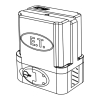
Detailed measurements and visual representation of the gate operator.

Gate Mechanical Preparation and Requirements

Gate Mechanics and Track Alignment

Ensuring gate leaf, wheels, track, and guides are properly prepared and aligned.

Duty Cycle Calculation and Motor Positioning

Gate Motor Installation Location Criteria

Guidelines for placing the motor considering environmental factors like water ingress.

Cabling Requirements and Diagram

Baseplate Installation and Fastener Kit

Baseplate Fastener Kit Assembly Details

Instructions for assembling the baseplate and its associated fastening components.

Conduit Height and Manual Release Operation

Manual Release Lever Engagement

Procedure for disengaging the gearbox using the manual release lever.

Setting the Gate's Closed Position Reference

Establishing the closed position as the system's origin point.

Mounting the Operator Unit and Gearbox

Operator Cover Removal and Gearbox Securing

Steps for accessing internal components and mounting the gearbox assembly.

Rack Installation and Pinion Alignment

Achieving Correct Rack-to-Pinion Mesh

Ensuring proper tooth engagement for smooth gate travel and synchronization.

Electrical Setup and AC Power Termination

220VAC Fuse Access and Replacement

Procedure for accessing and replacing the 0.5A fuse in the 220VAC power supply.

Control Card Wiring and Terminal Connections

Auxiliary Relay Wiring Examples and Limit Actuator Setup

Installing the Gate Travel Limit Actuator

Fitting the limit actuator to the rack for controlling gate travel endpoints.

Control Card Display and Dashboard Interface

Gate Operator Programming Menu Overview

Mandatory Gate Runtime Configuration

Safety Level and Infra-Red Beam Configuration

Setting Up and Enabling Safety Beams

Guide to activating and configuring the safety beam circuit for the gate.

BT Operating Mode and Auto-Close Time Settings

Pedestrian Mode: Opening Distance and Auto-Close Timer

Receiver Setup: Adding New Users and Transmitters

Programming New Transmitter Buttons

Steps to register remote transmitter buttons with the receiver unit.

Receiver Setup: 4-Function Transmitter Learn

Receiver Setup: Erasing Individual Remote Users

Receiver Setup: Master Erase of All Users

Receiver Setup: Diagnostics and Signal Testing

Receiver Setup: Version and Information Display

AC Monitoring and Charger Status Control

Slow Speed Travel Adjustment and Positive Close Mode

Configuring the Positive Close Feature

Instructions for enabling or disabling the positive close functionality.

Auxiliary Relay Operating Mode Selection

Collision Sensing and Safety Overload Behavior

Safety Infra-Red Beams: Operational Logic

Standard Mode BT Trigger Functions

Simple Auto-Close Mode BT Trigger Functions

Condominium Auto-Close Mode BT Trigger Functions

P.I.R.A.C. Auto-Close Mode BT Trigger Functions

PED Pedestrian Trigger (No Safety Beams)

PED Pedestrian Trigger (With Safety Beams)

Auxiliary Relay: Strike Lock Mode Details

Auxiliary Relay: Magnetic Lock Mode Details

Auxiliary Relay: Receiver Relay Mode Operation

Auxiliary Relay: Courtesy Light Mode Operation

Auxiliary Relay: Alarm Mode Configurations

Gate Forced Open Alarm Response

Auxiliary relay activation when the gate is physically forced open.

Positive Close Mode Functionality

Holiday Lock-out Mode Activation and Deactivation

Auto-Close Override and Party Mode

Status LED and Buzzer Indicator Guide

Troubleshooting: Display Codes and Solutions

Product Warranty Terms and Conditions

Related product manuals