9
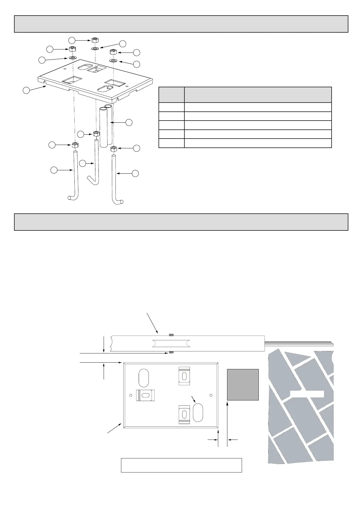
Baseplate and fastener kit assembly.
1
1
1
1
2
5
1
1
3
3
4
3
2
2
Diagram
number
Descripon
1 M10 Machine nuts.
2 M10 Flat washers.
3 M10 J-Bolts for concrete casng method.
4 Cabling conduit piping.
5 Baseplate.
Installing the baseplate.
There are a number of dierent fastening techniques that can be used to fasten the baseplate in posion. The standard kit is supplied with J-bolts
so that the baseplate can be cast in concrete. While this method oers a nice solid base it takes more than 48hrs to install as the concrete must cure
properly before connuing with the installaon. Whichever mounng method you opt for, the posion of the base plate will always remain the same.
Below are the dimensions to use when posioning the baseplate. The baseplate should be installed above the highest point of ooding that may occur
with the run o of water down the driveway.
PLAN VIEW OF THE BASEPLATE INSTALLED
Proudest component of
the gate on the motor side
Edge of the baseplate
nearest to the gate
Required space
30 - 50mm
Gate positioned where the proudest component
is opposite the base plate of the operator.
Base plate positioned on the opposite
side of the gate guide/emergency post,
to the driveway.
Gate guide/
emergency post
Driveway
Required space
> 50mm to allow for
the optional security
bracket.
Cable inlet.
 Loading...