8
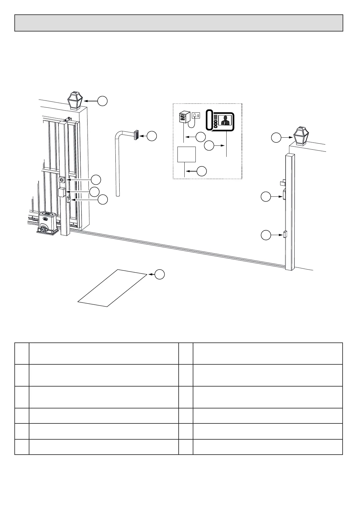
Cabling requirements.
• Before mounng the operator ensure your cables and conduing are in place to prevent any inconvenience at a later stage.
• All household mains cabling and circuits need to be installed by a qualied electrician and signed o by a registered electrician.
• Allow for spare cabling in case of faulty cable & breakages (especially important when using low specicaon cable).
• As automaon systems vibrate when in use, it is highly recommended that only mul-stranded, exible cables be used.
• If installing an intercom, remember to allow for sucient cable cores for all the users of the system as per manufacturers cabling requirements.
• The Drive 300 motor is designed to facilitate 1 x 20mm conduit going directly into its housing from below. If more cabling needs to be routed to the
motor, we suggest that a weatherproof electrical box be installed as a distribuon box. All of the circuits can then be extended to the distribuon
box and terminated there.
1
29V
3
Alarm
panel
2
11
4
10
8
9
1
6
5
7
1. Courtesy lights twin + earth 1.0mm back to motor housing and
isolator switch.
7. Free exit loop 1.5mm silicone insulated single core exible stranded
cable back to loop detector that is typically installed in the motor
housing.
2. Intercom gate staon (check with intercom supplier for cable
specicaons)
8. From intercom internal equipment (check with intercom supplier
for specicaons) + 5 cores 0,5mm stranded for status LED, BT and
Pedestrian triggers.
3. (220Vac) - twin + earth: 2,5mm stranded (An all pole negavely
biased isolator must be installed within 1,5m of the motor unit, in
circuit with the 220Vac supply)
9. Alarm monitoring circuit. 2 cores 0,5mm stranded back to motor
housing.
4. Safety infra-red beam RX power & switch. 4 cores 0,5mm stranded
back to motor housing.
10. Oponal plug in transformer for low trac sites (29Vac) - twin +
earth. Min 0,5mm stranded (1Amp)
5. Safety infra-red beam TX power. 2 cores 0,5mm stranded back to
motor housing.
11. Lock power supply. Twin + earth 2,5mm stranded from isolator
switch.
6. Electric lock power. 2 cores 0,5mm stranded back to independent
lock power supply via motor housing.
 Loading...