SIGNALING SYSTEM
6-12
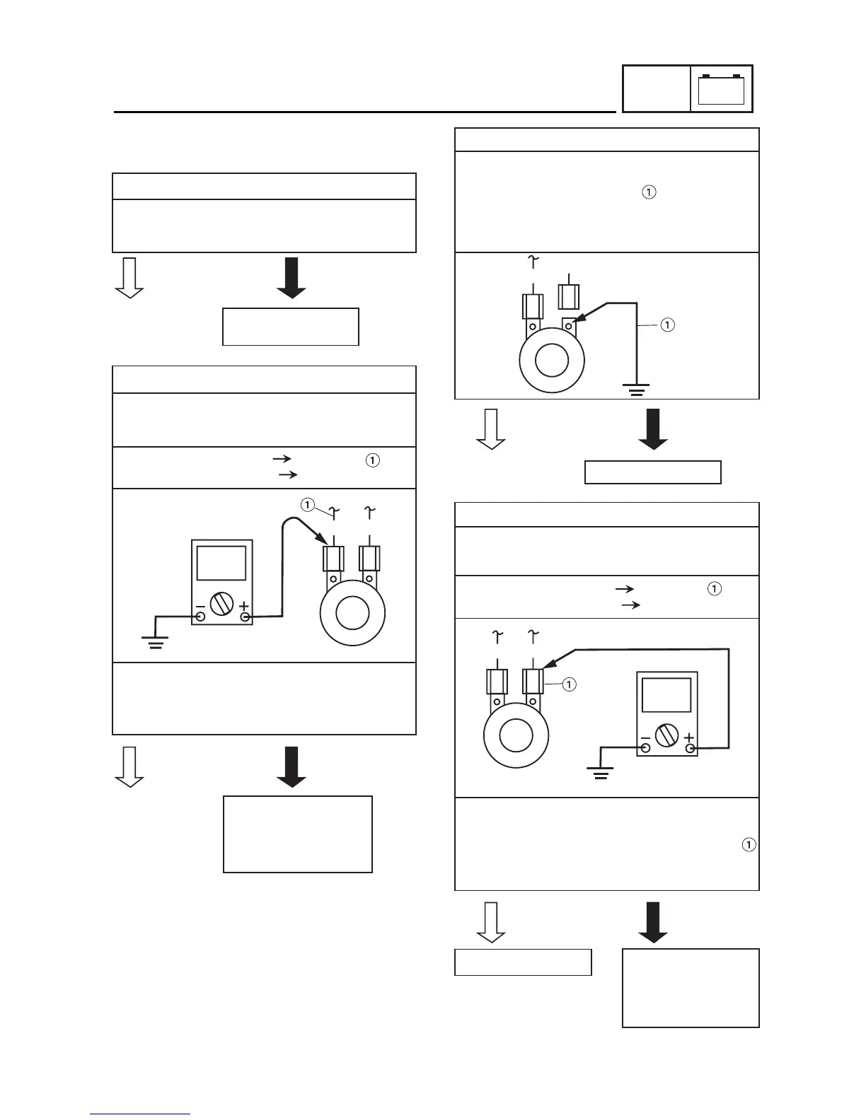
CHECKING THE SIGNALING SYSTEM
1. The horn fails to sound.
1. Horn switch
• Check the horn switch for continuity.
Refer to “CHECKING THE SWITCHES”.
• Is the horn switch OK?
2. Voltage
• Connect the pocket tester (DC 20 V) to the
horn connector at the horn terminal as
shown.
Positive tester probe
red/white
Negative tester probe ground
• Set the main switch to “ON”.
• Measure the voltage (DC 12 V) of brown at
the horn terminal.
• Is the voltage within specification?
3. Horn
• Disconnect the blue/yellow connector at
the horn terminal.
• Connect a jumper lead to the horn
terminal and ground the jumper lead.
• Set the main switch to “ON”.
• Does the horn sound?
4. Voltage
• Connect the pocket tester (DC 20 V) to the
horn connectors as shown.
Positive tester probe
red/white
Negative tester probe ground
• Set the main switch to “ON”. Push horn
switch
• Measure the voltage (DC 12V) of blue/yellow
at the horn terminal.
• Is the voltage within specification?
Replace the left
handlebar switch.
L/Y
R/W
The wiring circuit from
the main switch to the
horn connector is faulty
and must be repaired.
Replace the horn.
The wiring circuit or
horn switch is faulty
and must be repai-
red.
This circuit is OK.
YES
NO
YES
NO
YES
NO
YES
NO
–+
ELEC
R/W
R/W
L/Y
L/Y