i-on16 Installation
Page 9
Siting the Keypad(s)
Do site the keypad(s):
Within the area protected by the alarm system.
At a convenient height and location for the user.
Out of sight of potential intruders.
Do NOT site the keypad(s):
Next to electronic equipment, particularly
computers, photocopiers or other radio
equipment, CAT 5 data lines or industrial mains
equipment.
Where the cable run from the control unit will be
longer than 100m (see Cable Configuration and
Length).
Note: Do not fit any keypad with an internal prox
reader closer than one meter to any other type of
prox reader. This includes other keypads with prox
readers, external prox readers such as the KEY-EP,
or prox readers used by other systems (for example
access control systems). If you mount prox readers
closer together than one meter (including on the
other side of walls) then the two prox readers will
interfere and may not work correctly.
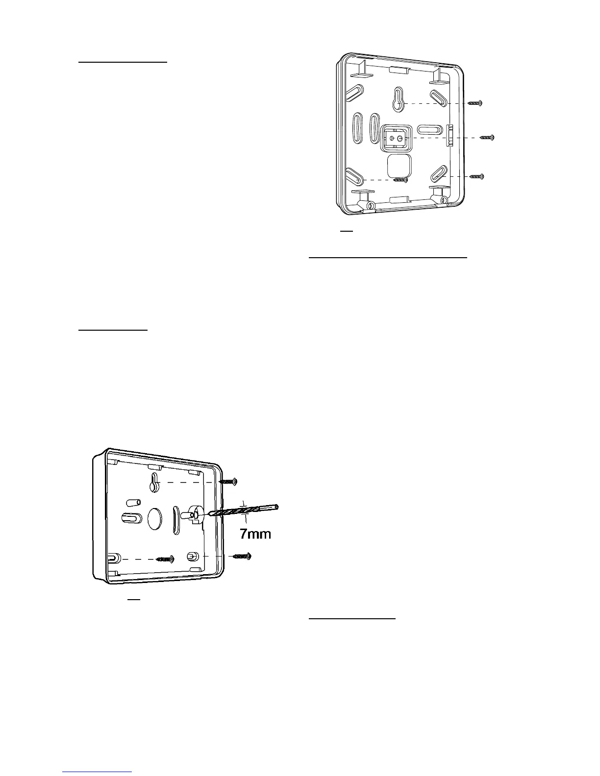
Fitting Keypads
Select which cable entry you are going to use and
break out the appropriate plastic sections.
Use 4mm x 25mm countersunk screws with a
thread suitable for the wall material in at least three
fixing holes when mounting the back of the keypad
on the wall.
i-KP01
If required, drill out the hole for the back tamper
using a 7mm bit (see Figure 16).
Figure
Screw KEY-K01/KP01/KPZ01 Back Box
to Wall
Connecting Keypads to Control Unit
Cable Type
In general, the control unit requires standard 7/0.2
un-screened alarm cable for wiring to keypads.
Screened cable may prove necessary if the
installation site has equipment that produces high
levels of R.F. (Radio Frequencies), for example
welding equipment. If screened cable is required,
you should keep to the following guidelines:
1. Avoid earth loops by connecting the screen on
the cable to mains earth at the end station but
not at the keypad.
2. The continuity of the cable screen is most
important and screens MUST be continuous
along the full length of the cable.
3. If the cable enters any metal enclosure, ensure
the screen is isolated from the case.
Cable Segregation
Segregate the keypad cabling from any other
wiring, such as mains supply cables, telephone
cables, computer network cables and R.F. cables.
Use cable ties to keep cables separated.
Keep the keypad cable clear of cables supplying
sounders or extension loudspeakers.
Cable Configuration and Length
You can connect up to two keypads to the end
station. You may connect the keypads either
serially, or in parallel at the end station connector.
The cable length from control unit to the most
distant keypad should not exceed 100m.
Keypad Connection
Figure 18 shows the wiring connections at the
keypad and control unit.

 Loading...


