i-on16 Before You Begin
Page 3
handle the PCB, take the standard precautions
against damage by static electricity.
To gain access to the interior of the end station
undo the two screws at the top of the case. Pull the
top of the lid down, and then lift the lid out of the
retaining lugs at the bottom of the case (see Figure
1.)
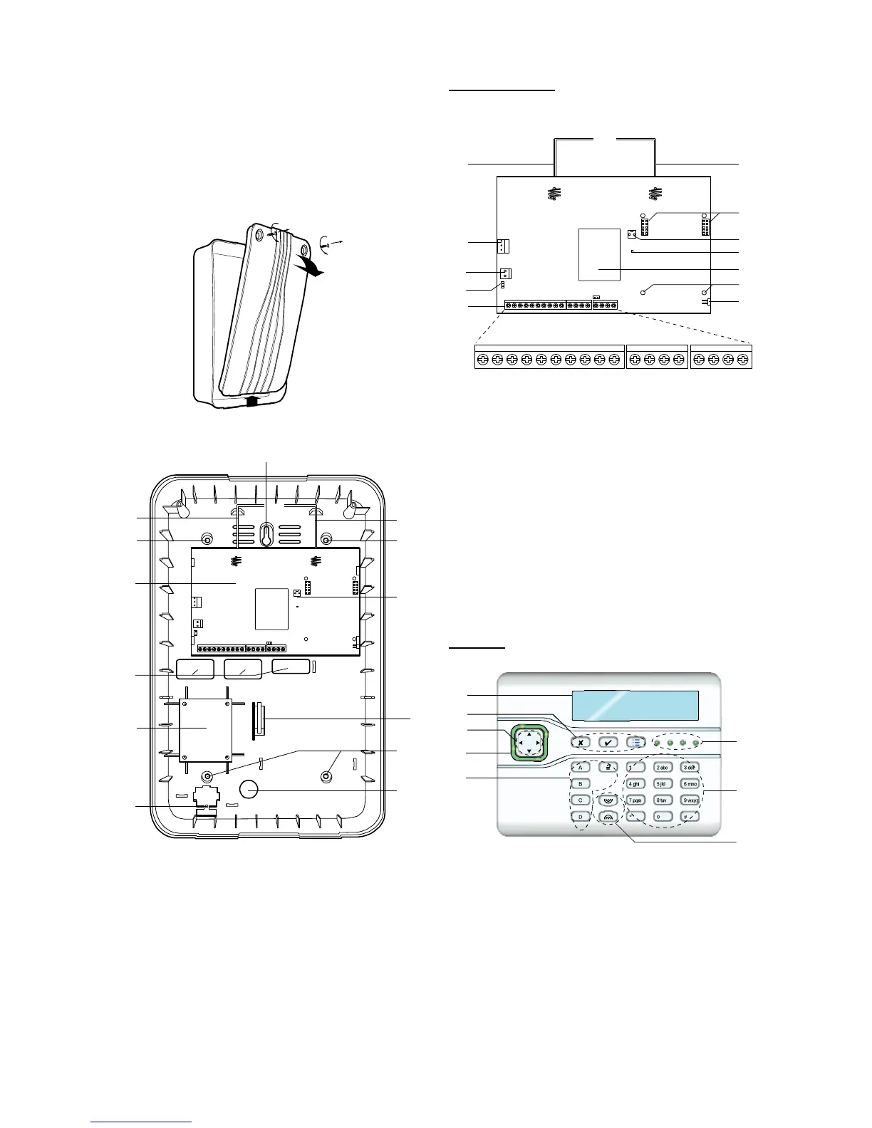
Figure 2 shows the interior of the end station.
Figure
Opening the Control Unit
1. Central fixing keyhole.
2. Aerials.
3. Fixing holes.
4. Printed circuit board (PCB).
5. Cable entry holes for PCB.
6. Transformer.
7. Mains connector block.
8. Cable entry hole for mains.
9. Back Tamper switch (if fitted).
10. Connector pins for Lid Tamper.
Figure
Control Unit
End Station PCB
Figure 3 shows the controls and connectors
available on the end station PCB.
1. Aerials.
2. 20VAC Input (from transformer).
3. Battery input (12VDC).
4. Kick start pins.
5. Connector block.
6. Reset codes pins.
7. Holes for module support pillars.
8. RF receiver.
9. “Heartbeat” LED.
10. Connector pins for tamper switch.
11. Sockets for communicator (I-SD01).
Figure
End Station Printed Circuit Board
Keypads
i-kp01 Controls and Displays
1. LCD display (2 x 20 characters).
2. Programming keys.
3. Navigation keys
4. Alert LEDs
5. Setting and unsetting keys.
6. Programmable HUA keys.
7. Number/text keys.
8. Set/Unset LEDs.
Figure
0V 0V 12V 12V0V 12V A B0V 12V 1 2 3 4
TR14V4 - LS +
AUX AUXBUSAUX OUTPUTS
2
3
5
9
11
8
6
7
11
4
10

 Loading...


