Before You Begin i-on16
Page 6
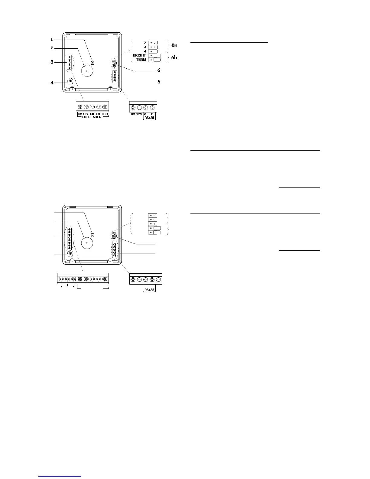
1. Tamper switch.
2. Sounder.
3. Connector for KEY-EP.
4. Sounder volume control.
5. Connector for control unit bus.
6. Jumpers for:
6a Addressing (not used in i-onEX control
units).
6b LED functions and RS485 bus
termination.
Figure
KEY-KP01 Keypad PCB
1. Tamper switch.
2. Sounder.
3. Connector for KEY-EP. Terminals for zones
4. Sounder volume control
5. Connector for data bus and output terminal.
6. Jumpers for addressing and LED function:
6a Addressing
6b LED functions and RS485 bus
termination.
Figure
KEY-KPZ01 Keypad PCB
Power Availability
Before connecting any external devices to the
control unit, you must make sure that the control
unit can provide sufficient current to power the
system during a mains failure for the time required
to meet Grade 2 PD6662 or EN50131-1. The
standard requires 12 hour standby, which includes
two periods of 15 mins in alarm.
The amount of current available from the control
unit depends on the battery fitted. The current taken
by the control unit PCB, communicator and keypads
is given in Technical Specifications on page 22.
For example: in an alarm system with an i-on16
control unit and two i-kp01 keypads the system
takes the following total quiescent current:
i-sd01 communicator (quiescent)
2 x i-kp01 at 30mA each
(backlights off)
During an alarm, these figures become:
2 x i-kp01 at 30mA each
(backlights off)
The total amp hours required =
(0.235A x 11.5h) + (0.730A x 0.5h) = 3.07Ah
A fully charged 7Ah battery can provide this amount
of charge.
In this example a 7Ah battery should exceed the
Grade 2 requirements.
Note: All current drawn from the Aux terminals (12V
and 14.4V) must be included in the overall
calculation.
2
3
4
BRIGHT
TERM
0V 12V A B
0V 12V D0 D1 LED
EXT READER
Z1 Z2
OP
1
6a
6b
3
4
5
6
2

 Loading...


