Installation i-on16
Page 14
If you wish run mains cable through the side of the
case, make sure that they are horizontal for the last
metre before entering the case.
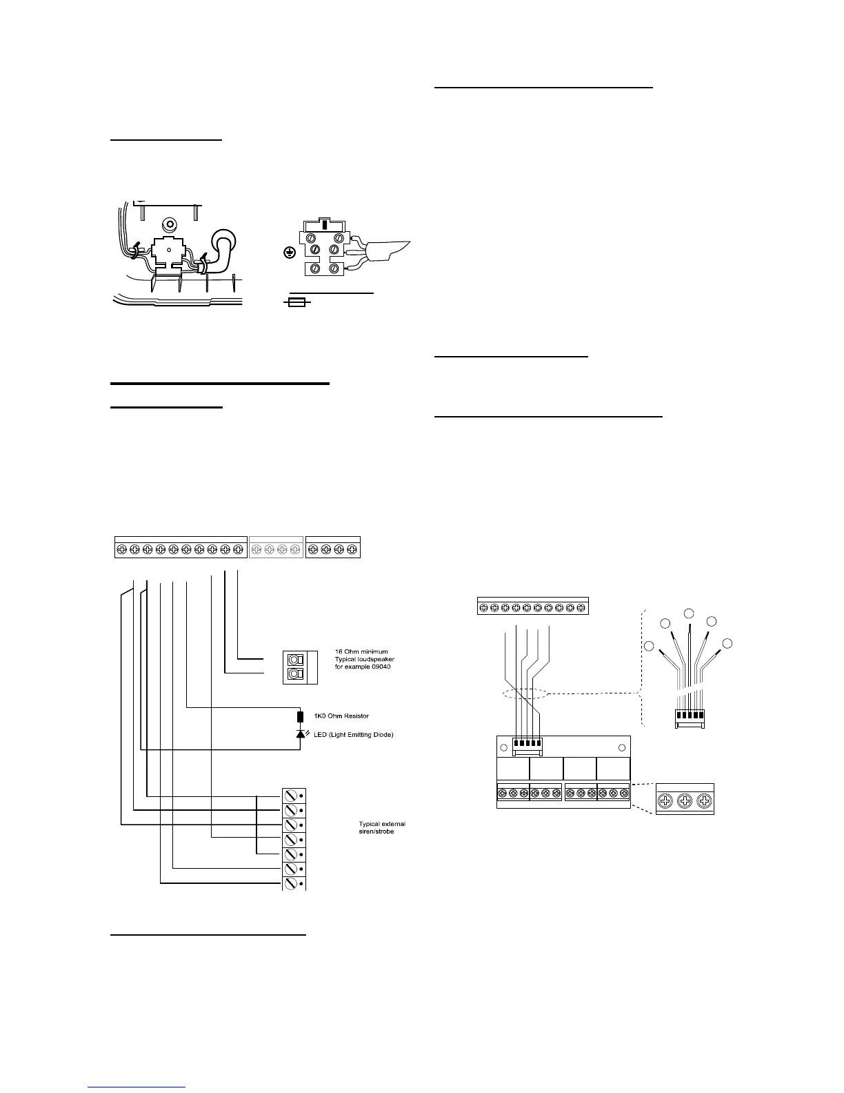
Mains Connection
Figure 28 shows the mains connection. Connect to
a suitable supply using a double pole disconnect
(isolation) device in accordance with EN60950-1.
Figure
Mains Connection
Caution: Do not apply power at this point.
Step 4. Connect Wired
Peripherals
The end station PCB provides four connectors for
wired outputs. Each of these outputs is driven by a
transistor, and is capable of sinking a maximum
500mA when active. The outputs are 0V when
active, +12V when inactive.
Figure 29 shows examples of connecting wired
peripherals.
Figure
Connecting Wired Peripherals
Remote Loudspeaker (Optional)
If you wish to add a wired Loudspeaker unit, then
connect it as shown in Figure 29.
Wired External Sounders (Optional)
Wired external sounders differ in their methods of
connection. Figure 29 shows an example of a
general method of using the outputs to connect a
wired sounder.
It is possible to program the TR terminal on the
control unit (see Figure 3) as either CC or FSL. Use
Installer Menu – System Options – Panel Tamper Rtn.
By default the terminal is CC. If you program the TR
terminal as FSL then make sure you connect a 2k2
resistor in series with the wire to the sounder.
Note: If you do not wish to connect a wired external
sounder then leave TR programmed as CC and
make sure you link TR to 0V on the control unit.
This prevents the control unit reporting Bell Tamper
unnecessarily.
Wired Outputs (Optional)
Figure 29 shows an example of using the wired
outputs to drive an indicator LED.
Fit and connect the I-RC01 (Optional)
Eaton’s Security Business provides the I-RC01
relay card for use when connecting the outputs to
devices that require voltage free contacts on their
inputs. The I-RC01 is supplied with a short wiring
loom that provides connections to each relay trigger
input (see Figure 30). A single wire allows you to
connect the module to the 12V +ve aux supply in
order to provide power for all four relays. The
terminals on the edge of the card provide
connections to the Normally Open, Common and
Normally Closed terminals of the relays.
Connecting an I-RC01 Module
Once you have connected the wiring loom of the I-
RC01 to the control unit output terminals then slide
I-RC01 PCB into one of the two slots provides at
the side of the control unit case.

 Loading...


