Keypad Addressing Jumpers
To add a new wired keypad to the bus of an existing
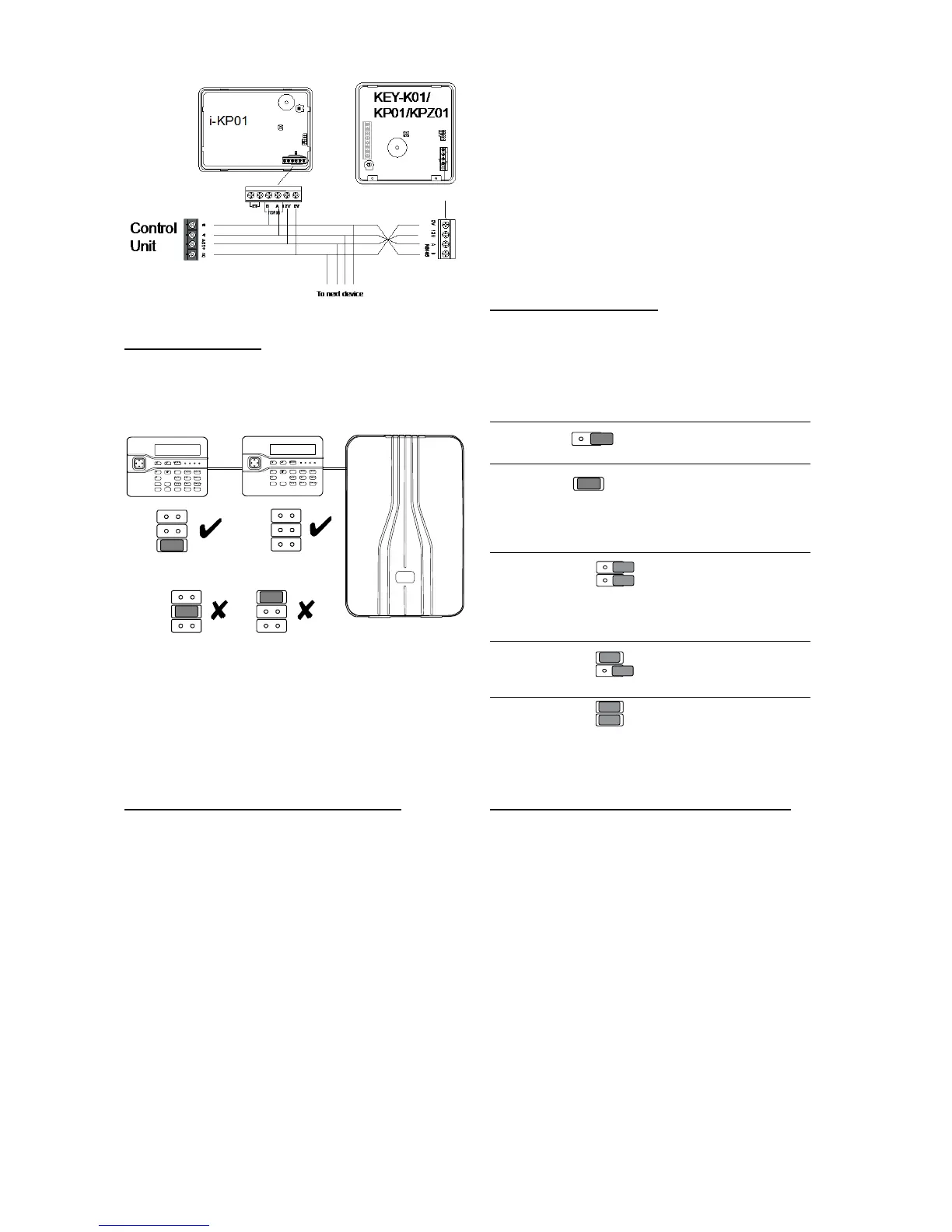
i-on16 installation, first remove all power from the
control unit, both mains and battery. Make sure the
address link on the new keypad is not fitted in the
same position as the address links on the keypad
already connected to the control unit. Connect the
new keypad and then apply power to the system.
Re-using a V2.0 Keypad From an i-onEX
If you wish to use an i-kp01 that has previously
been working on an i-onEX system, then you must
first default the keypad address. Eaton’s Security
Business recommend that you do this by deleting
the keypad from the i-onEX system using the
Installer Menu. However, if this is not possible then
you must default the keypad address manually as
follows:
1. Remove the power and data connections from
the keypad to the system bus.
2 Open the keypad and make sure that the
keypad tamper switch is open. (It must stay
open until step 9.)
3. Apply 12Vdc power to the 0V and 12V terminals
on the keypad connector. DO NOT use the i-
on16 bus for this.
The navigation key LEDs flash rapidly.
4. Hold down keys D and at the same time.
After a few seconds you should hear a
confirmation tone and the navigation LEDs start
flashing about once per second.
5. Release the D and keys.
6. Remove the 12V dc power from the keypad.
7. Select an address for the keypad by placing a
jumper on the appropriate address pins (see
Figure 19).
8. Connect the new keypad (see Figure 18).
9. Close the keypad and ensure that the tamper
switch is closed.
Backlight Control i-kp01
You can control the appearance of the keypad
backlights and set/unset LEDs by fitting links over
the appropriate jumpers on the keypad PCB (see
Figure 7 on page 4 for the position of the jumpers).
The jumpers have the following functions:
Note: To comply with PD6662:2010 at Grade 2,
disable the ABCD LEDs.
Backlight Control for KEY-K01/KP01/KPZ01
You can control the brightness of the keypad
backlights by fitting links over the BRIGHT jumper
on the keypad pcb (see 1b in Figure 11 or 6b in
Figure 13).
Jumper OFF The keypad backlights glow at
normal intensity.
Jumper ON The keypad backlights glow extra
bright.
Programming Backlight, ABCD LEDs and
Navigation LEDs From the Keypad
You can set the function of the backlights in either
of two ways:
a) Use the Installer Menu – Detectors/Devices – Wired
Keypads – Edit Keypad – (Keypad n) – Backlight option.
See the Engineering Guide for more details.

 Loading...


