INPUT ISOLATION TRANSFORMER INSTALLATION
EATON Powerware
®
9155 UPS (8–15 kVA) User’s Guide S 164201553 Rev F www.powerware.com
20
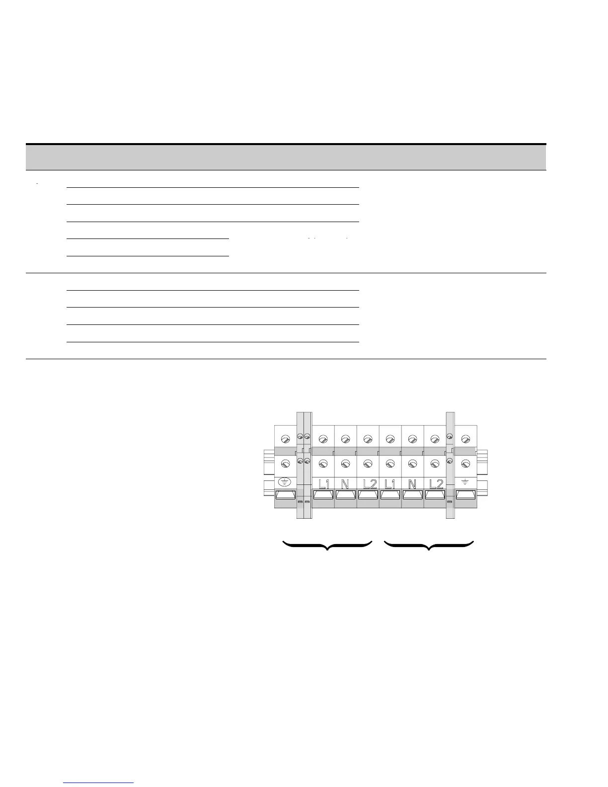
12. Wire the output of the input isolation transformer terminal block to the UPS input
terminal block (see Table 3 and Figure 11).
Table 3. UPS Terminal Block (TB1) Wiring
Wire Function Terminal Position Minimum Wire Size* Tightening Torque
Conduit Connection
(Entry Size)
Input
Ground TB1-1 8AWG
AUX TB1-2-1 and 2-2 —
Not Used TB1-2A-1 and 2A-2 —
2
lb in 2” access hole for
L1
TB1-3
8kVA 4AWG(21.2mm
2
)
(2.83 Nm)
1-1/2” conduit
Neutral
TB1-4
10 kVA
3AWG(26.7mm
2
)
2
L2 TB1-5
15 kVA
.
2AWG(33.6mm
2
)
Output
L1 TB1-6 8AWG
Neutral TB1-7 8AWG
L2 TB1-8 8AWG
25 lb in
2” access hole for
-
”
Not Used TB1-8A-1 and 8A-2 —
.
m
-
con
u
Ground TB1-9 8AWG
*Useonly75°C-rated copper wire. Minimum wire size is based on 120/208 full load ratings applied to NEC Code Table 310-16. Code may require a larger
AWG size than shown in this table because of temperature, number of conductors in the conduit, or long service runs. Follow local requirements.
13456789
Input
TB1
2
2A
8A
Output
Figure 11. UPS Terminal Block
13. Replace the UPS wiring access cover and the input isolation transformer wiring
cover.
14. Continue to “Stabilizing the Cabinet” on page 43 to complete the UPS
installation.
15. On the input isolation transformer, punch one pilot hole in t he conduit landing for
the input conduit using a Greenlee punch or similar device (see Figure 10 on
page 19).
16. Install the supplied edge grommet in the top of the input isolation transformer
wiring cover.