Chapter 6—Installation Requirements
DG1 Series VFD MN040002EN—March 2014 www.eaton.com 37
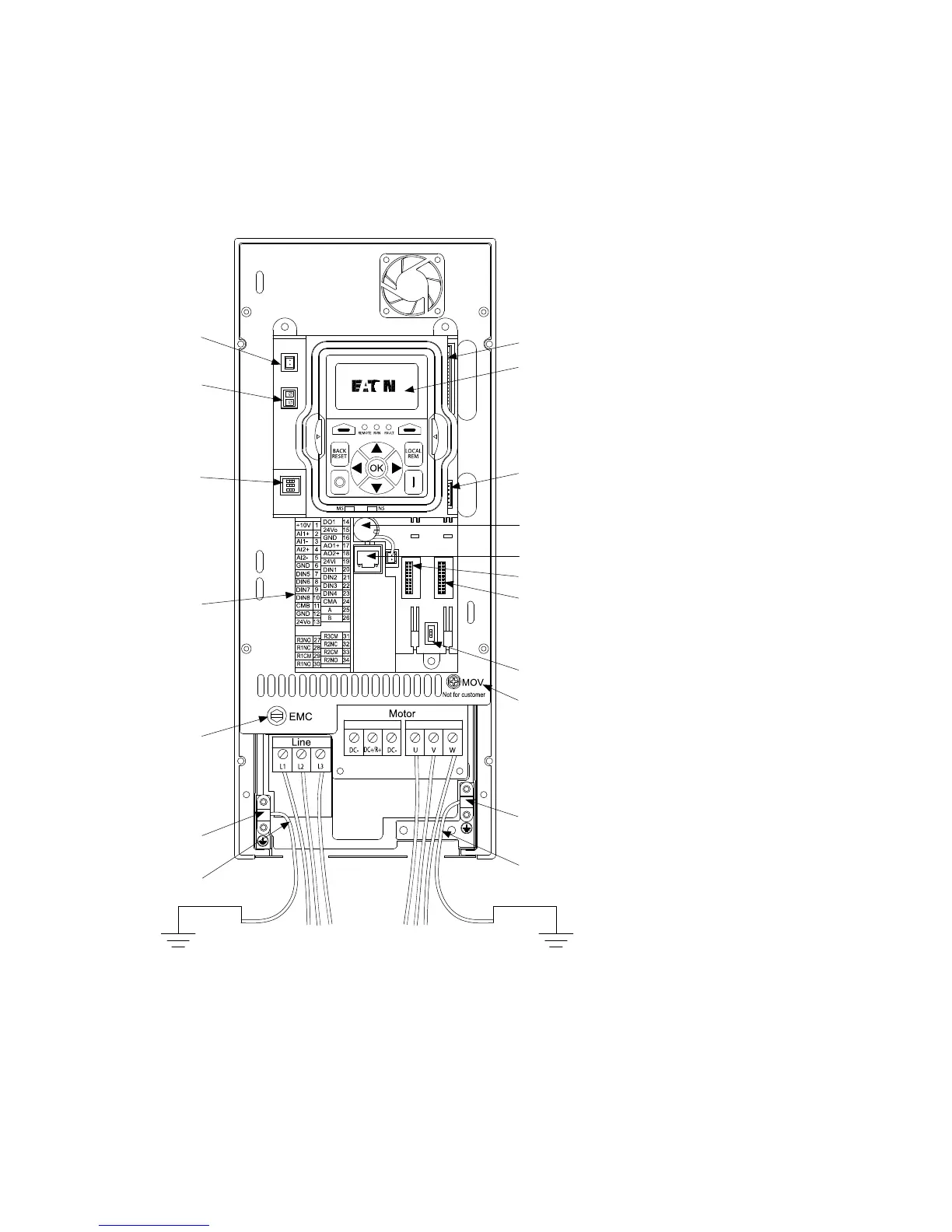
Control Board
The main DG1 Series VFD consists of a main control board,
control I/O connections block and two slots for extra option boards.
Figure 22. DG1 Series Adjustable Frequency Drive
Control Wiring
●
All control I/O wiring must be segregated from line (mains)
and motor cabling
●
Control wiring shall be shielded twisted pairs to meet
EMC levels required by IEC/EN 61800-3 (2004)
●
Run 240 Vac and +24 Vdc control I/O in separate conduit
●
Control I/O terminals must be tightened to 4.5 in-lb (0.5 Nm)
●
Wiring or ferrule size: 28~12 (Sol) AWG, 30~12 (Str) AWG,
or 0.2~2.5 mm
2
Connect DSP Part
to Power Board
Keypad
Connect MCU Part
to Power Board
Battery (Standard)
RJ45 EtherNet/IP, BACnet,
IP Modbus TCP
Optional Card A
Optional Card B
RS-485 Terminating
Resistor
Removable
MOV Screw
Motor Ground
Clamp Location
Grounding
Strap Location
Grounding
Strap Location
Line Ground
Clamp Location
Removable
EMC Screw
Control I/O
Terminals
AI Mode Selection
STO
Fan Power Wire
Line Side Motor
Line Ground
Clamp Location
ON
123
ON
1

 Loading...


