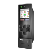
SC100 Handbook
Copyright © 2008-2011 Eaton Corporation. All Rights Reserved.
IPN 997-00012-63C August 2011
System Alarm Configuration
The following system alarm parameters can be configured.
Set to Disabled if no indication is required when the
alarm is active. Or, set to the required alarm priority.
See details on page 32.
DCTools: Alarms > Alarm
State
If required, select a digital output (relay) that will be
operated when the alarm is active.
If required, select a second digital output (relay) that
will be operated when the alarm is active.
AC Fail
Recognition Period
An ac supply failure condition must be continuously
active for this period before an AC Fail alarm is
generated.
DCTools: Alarms > Alarm
Configuration
Enable High Float
Tracking
The High Float alarm threshold will be adjusted when
the operating voltage is changed by a voltage control
process.
High Float alarm is activated if the bus voltage is
above this value.
Enable Low Float
Tracking
The Low Float alarm threshold will be adjusted when
the operating voltage is changed by a voltage control
process.
Low Float alarm is activated when the bus voltage is
below this value.
High Load alarm is activated if the bus voltage is
above this value.
Low Load alarm is activated if the bus voltage is below
this value.
Battery Fuse Fail
Active State
Specifies if the alarm activates from an open or closed
contact.
Battery
Temperature High
Threshold
Battery Temperature High alarm is activated if the
battery temperature is above this value.
Battery
Temperature Low
Threshold
Battery Temperature Low alarm is activated if the
battery temperature is below this value.
System Overload
Recognition Period
System Overload
Threshold
AC High alarm is activated if the ac voltage is above
this value.
AC Low alarm is activated if the ac voltage is below
this value.

 Loading...


