12/135
EN
Note: UT is the a.c. mains voltage prior to application of the test level.
Conducted RF
IEC 61000-4-6
Radiated RF
IEC 61000-4-3
3Vrm
150kHz-80MHz
10V/m
80MHz-2.7GHz
3Vrm
10V/m
Portable and mobile RF
communications equip-
ment should be used no
closer to any part of the
device, including cables,
than the recommended 30
cm separation distance.
Recommended Separation Distances Between Portable and Mobile RF Communications Equipment and
This Device
This device is intended for use in electromagnetic environments in which radiated RF disturbances are
controlled. The user of this device can help prevent electromagnetic interference by maintaining a minimum
distance between portable and mobile RF communications equipment (transmitters) and this device as out-
lined below, according to the maximum output power of the communications equipment.
RATED MAXIMUM
OUTPUT POWER OF
TRANSMITTER WATTS
SEPARATION DISTANCE ACCORDING TO FREQUENCY OF TRANSMITTER
METERS
150KHZ~80MHZ
D=1.2
80MHZ800MHZ
D=1.2
800MHZ2.5GHZ
D=2.3
0.01 0.12 0.12 0.23
0.1 0.38 0.38 0.73
1 1.2 1.2 2.3
10 3.8 3.8 7.3
100 12 12 23
For transmitters with maximum output power not stated above, the recommended separation distance
(d) in meters can be estimated using the formula applicable to the transmitter frequency, where P is the
maximum output power rating of the transmitter in watts (W) provided by the transmitter manufacturer.
NOTE 1: At 80 MHz and 800MHz, the separation distance for the higher frequency range applies.
NOTE 2: These guidelines may not apply in all situations. Electromagnetic propagation is a ected by ab-
sorption and refl ection from buildings, objects and people.
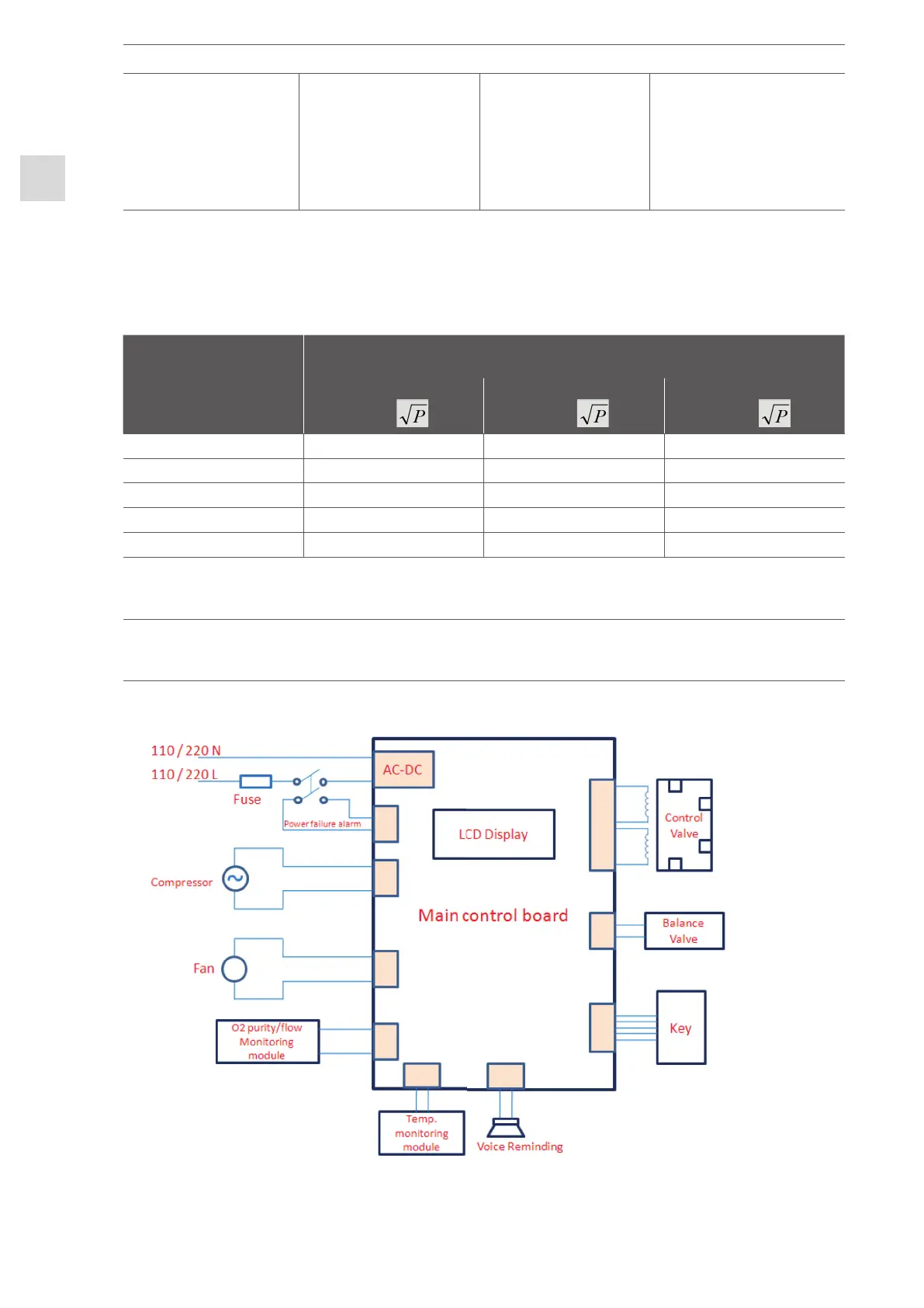
APPENDIX B: CIRCUIT DIAGRAM
 Loading...