4.1 Construction
4.1.1 Overview
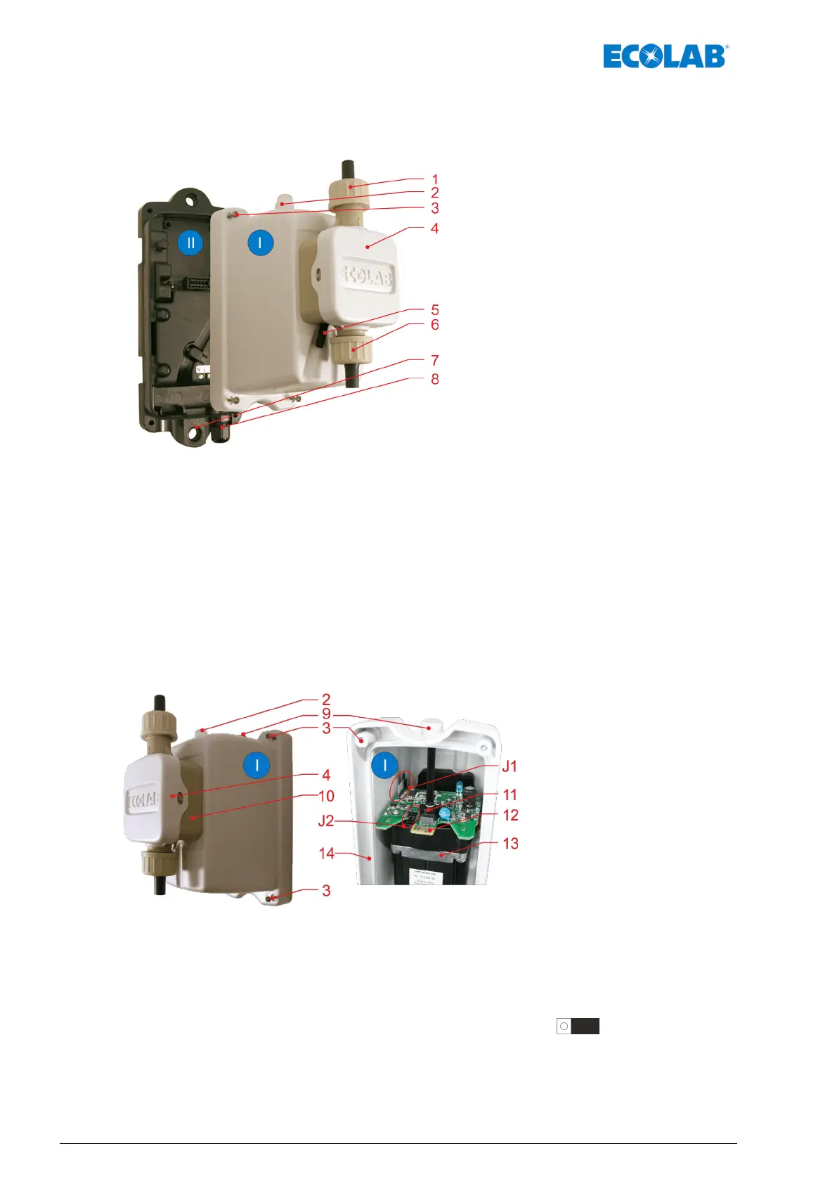
Fig. 2: Construction Turbo SMART II
I Pump module
Ä
Chapter 4.1.2 ‘Pump module’ on page 22
II Back cover module
Ä
Chapter 4.1.3 ‘Back cover modules’ on page 23
1 Coupling nut (connection on discharge side)
2 LED signal
3 Housing screw (4 x)
4 Pump head (cover)
5 Safety drain (for diaphragm failure)
6 Coupling nut (connection on intake side)
7 Mounting lug (2 x)
8 Cable bushing for power supply connection
for 24 V DC or 230 V AC depending on version.
Ä
Chapter 4.1.3 ‘Back cover modules’ on page 23
4.1.2 Pump module
Fig. 3: Pump module
I Pump module
2 LED signal
3 Housing screw (4 x)
4 Pump head (cover)
9 Cover plug for speed adjustment
10 Pump head
11 Potentiometer (Poti)
12 Motor board
13 Pump motor
14 Labyrinth seal
J1 Jumper “pump head adaption”
J2
Jumper “capacity” ( as delivered)
Functional description
22Rev. 5-06.2018
 Loading...