5.2.1 Connection: Suction and Pressure Lines
DANGER!
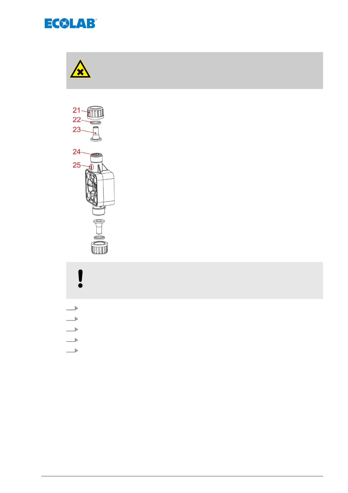
When connecting the suction and pressure lines, make sure that the O-rings
(pos 24) are installed on the connections to obtain the necessary seal.
Pos. Description
21 Union nut PP, Article no. 34500228 (EBS no. on request)
or
Union nut PVDF, Article no. 35200167 (EBS no. on request)
22 Clamp, Article no. 38610409 (EBS no. on request)
23 Taper part PP, Article no. 38610408 (EBS no. 10000482)
or
Taper part PVDF, Article no. 38610415 (EBS no. on request)
24 O-Ring (Ø 12 x 2,5 mm) - EPDM, Article no. 417001102 (EBS no. 10002916)
or
O-Ring (Ø 12 x 2,5 mm) - FPM, 417003334 (on request)
25 Pump head direction of flow (indicator arrow)
NOTICE!
When connecting the suction and pressure lines, pay attention to the flow
direction shown by the arrow stamped on the pump head!
1. Cut the line off evenly.
2. Slide union nut (pos. 21) and clamp (pos. 22) over the line.
3. Press the line onto the cone (pos. 23) until it stops at the shoulder.
4. Check that the O-ring (pos. 24) is in the valve groove.
5. Tighten the union nut (pos. 21) by hand only (no tools!).
Device Installation
27 Rev. 5-06.2018
 Loading...