5
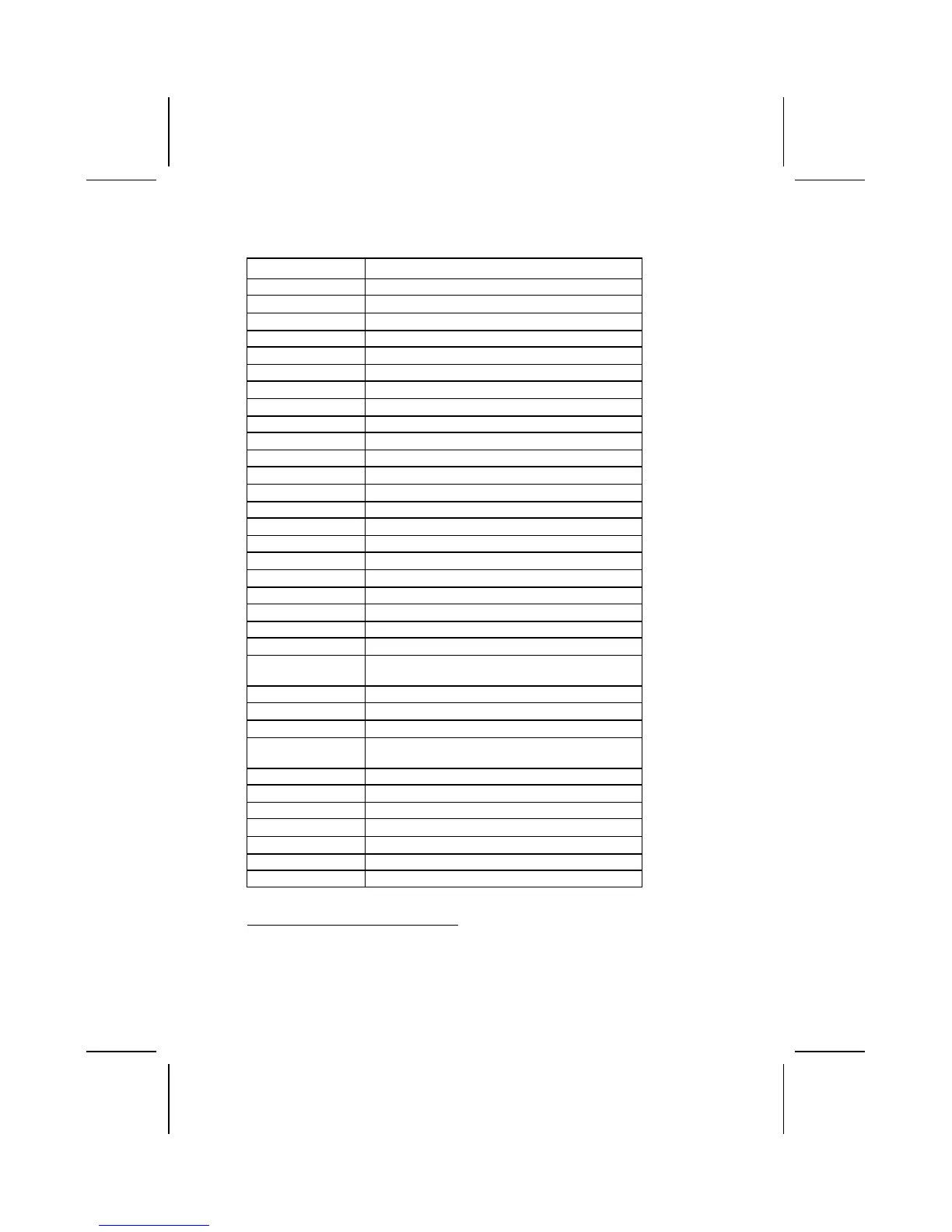
Table of Mainboard Components
Label Component
AGP1 Accelerated Graphics Port
ATX1 Power connector
AUDIO Front Audio Connector
BT1 Three volt realtime clock battery
CASEFAN Case Fan header
CD1 Primary CD-in connector
CD2 Secondary CD-in connector
CNR1 Communications Networking Riser slot
CPU1 Socket A for AMD Athlon/Duron CPUs
CPUFAN Cooling fan for CPU
DDR1~DDR3 Three 184 pin DDR SDRAM
FDD1 Floppy disk drive connector
FIDJP CPU ratio select jumper
IDE 1 Primary IDE channel
IDE 2 Secondary IDE channel
SIR Infrared cable header
JP1 Clear CMOS jumper
JP2 KB wake-up function header
JP3 BIOS protection jumper
LED1
1
Memory module LED
LAUDIO MIC/Speaker-out connector
LSIR Serial infrared port
LPANEL Connector for case front panel switches and LED
indicators
LUSB1/LUSB2 Connector for front panel USB ports
LMSG Message LED header
LSMI MSG LED header
PANEL Connector for case front panel switches and LED
indicators
PCI1 ~ PCI5 Five 32-bit add-on card slots
PWRFAN Power Fan connector
SJ Single LED header
SPKR1 Speaker connector
USB2/USB3 Front panel USB headers
WOL1 Wake On LAN wakeup connector
WOM1 Wake On Modem wakeup connector
1
The red indicator LED1 turns on if your system is still pow-
ered, at which time memory modules cannot be installed or
uninstalled.