Chapter 6
| Switch Management
Understanding the System Status LEDs
– 47 –
Understanding the System Status LEDs
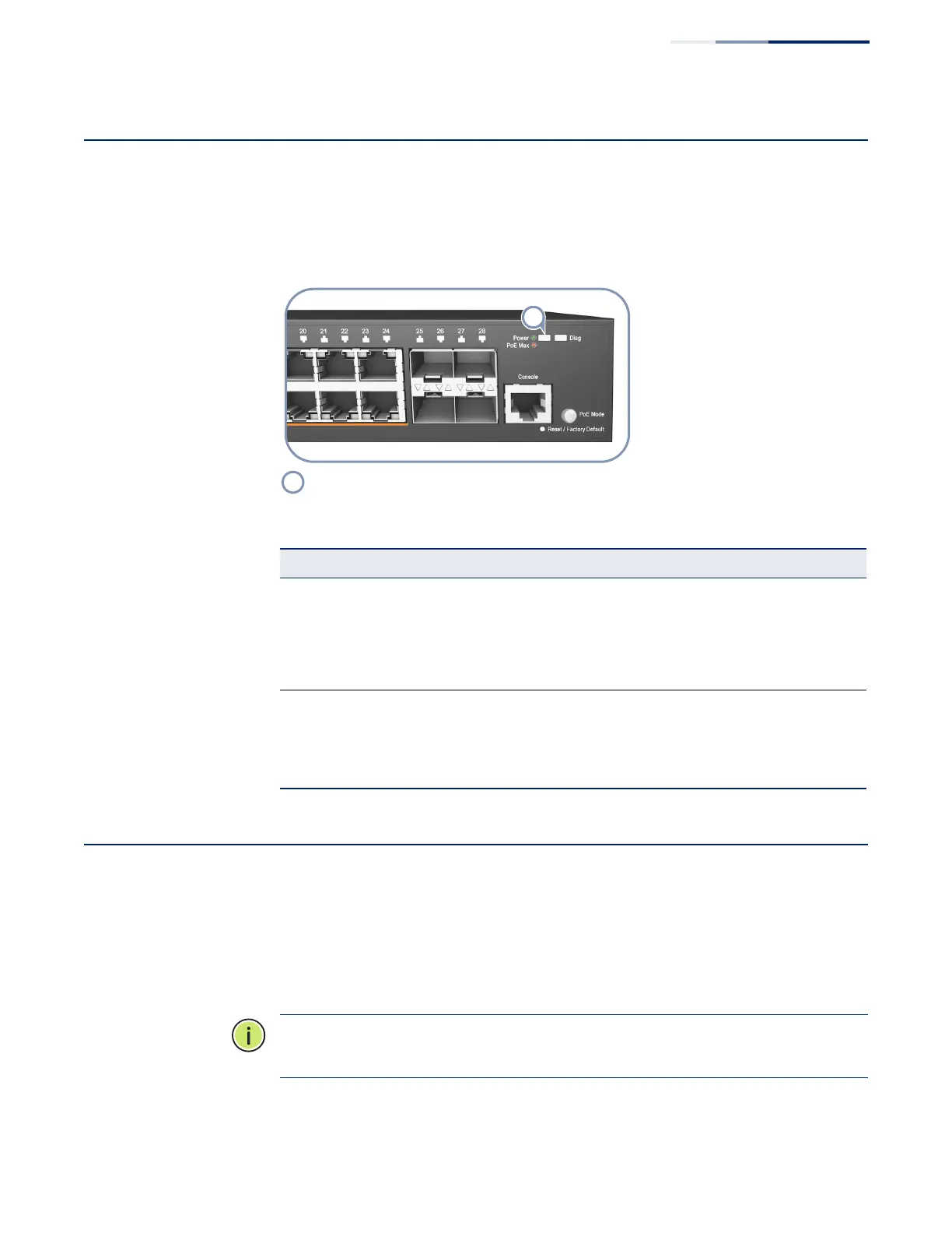
The switch includes a display panel of key system LED indicators. The LEDs, which
are located on the front panel, are shown below and described in the following
table.
Figure 24: System LEDs
How to Connect to the Console Port
The RJ-45 Console port on the front panel of the switch is used to connect a
console device to the switch for out-of-band console configuration. The console
device can be a PC or workstation running a VT-100 terminal emulator, or a VT-100
terminal. A console cable is supplied with the switch for connecting to a PC’s
RS-232 serial DB-9 DTE (COM) port.
Note:
To connect to notebooks or other PCs that do not have a DB-9 COM port, use
a USB-to-male DB-9 adapter cable (not included with the switch).
System Status LEDs.
Table 10: System Status LEDs
LED Condition Status
Power/PoE Max On Green Internal power operating normally.
On Amber The PoE device power draw on the switch has reached the
system limitation.
Off No AC power is connected or the internal power supply
has failed.
Diag
(Diagnostic)
(ECS2100-10T/
P/PE/28T/P/PP/
52T/ECS2110-
26T)
Flashing Green System diagnostic in progress.
On Green The system diagnostic test has completed successfully
Off System boot up failed.
 Loading...