2205 System Technical and User’s Guide
Document : 0022175 Rev A Page 6
4. System Block Diagram
A typical system block diagram, drawing 0021988, depicts the major external system components and
connectivity relative to the system purchased. Please refer to this when considering system specific
replacement parts and cabling. The typical 2300 tri-frequency pressure housing assembly is depicted in
drawing 0021987. While the bottle is built for the 2300 system, the interior electronics are standard 2205.
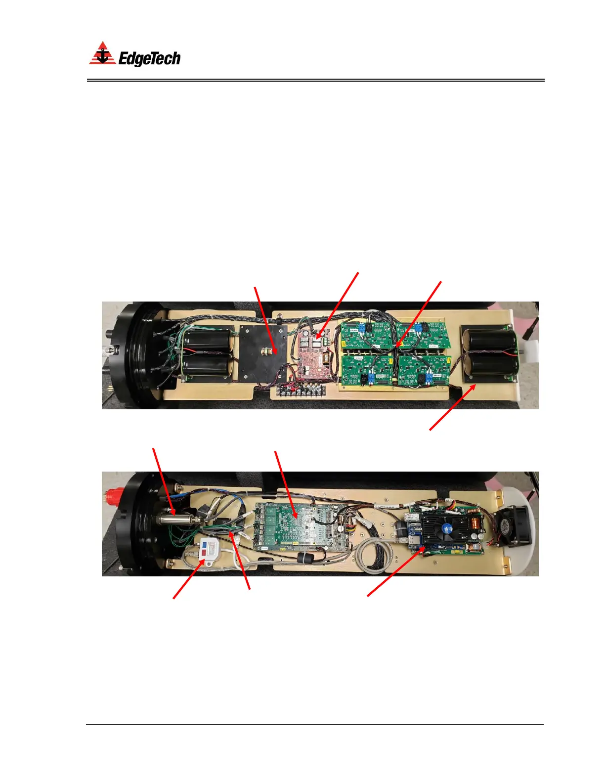
Figure 4-1 depicts the internal system components found in the pressure housing. There are no user
serviceable components within the pressure housing. Contact customer service for any system issue.
Figure 4-1. Processor Electronics