B344-21-880 Issue N
Page 4 © Edwards Limited 2007. All rights reserved.
Edwards and the Edwards logo are trademarks of Edwards Limited.
Introduction
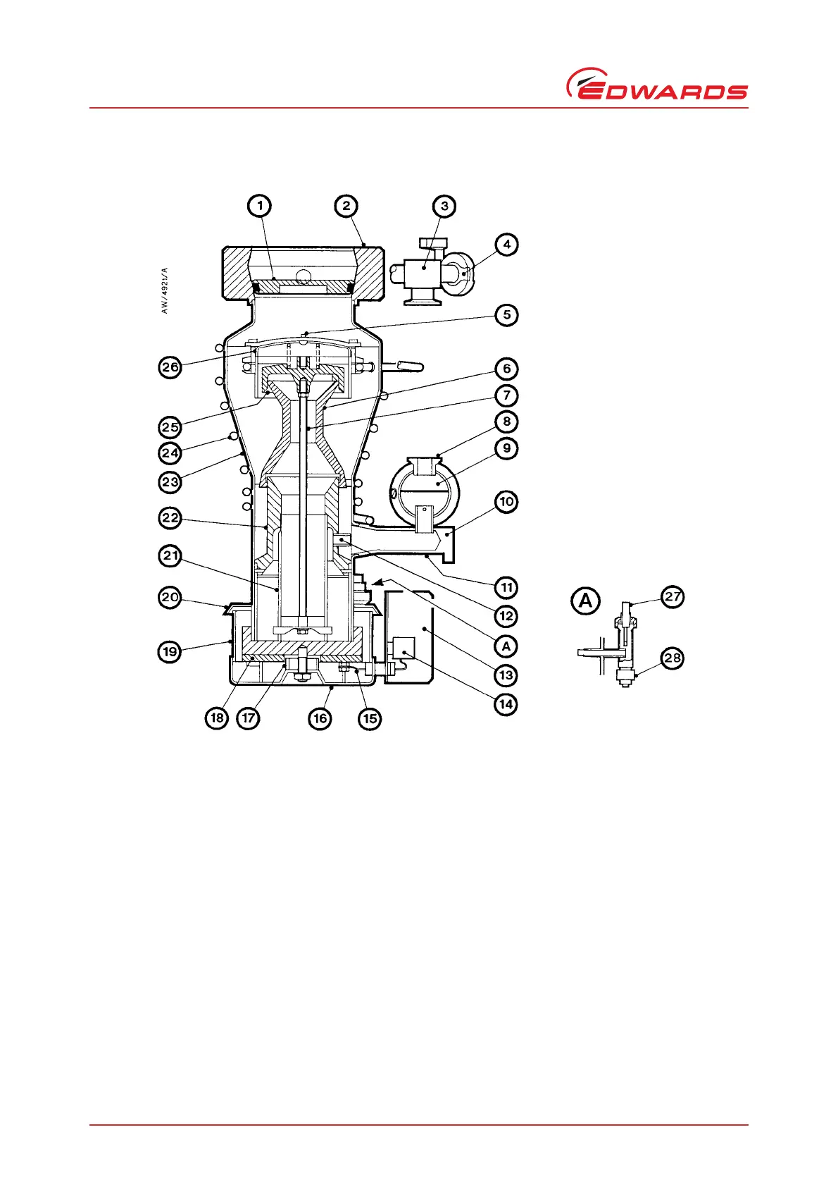
Figure 1 - Sectional view of valved Diffstak 63/150 pump
1. High-vacuum isolation-valve
2. Inlet-flange
3. Roughing connection
4. Gauge connection (NW10)
5. Retainer strap
6. 2nd-stage jet assembly
7. Tie-rod
8. Backing connection
9. Backing condenser
10. Pump-ready switch mounting
plate
11. Backing spout
12. Ejector jet
13. Terminal-box
14. Terminal-block
15. Electrical cables
16. Heater assembly
17. Spacer
18. Heater
19. Pump-boiler
20. Radiation shield
21. Vapour-tube
22. 3rd-stage jet assembly
23. Pump-body
24. Water-cooling coil
25. Top-jet assembly
26. Baffle-cap
27. Fluid filler and dipstick
assembly
28. Fluid drain