© Edwards Limited 2007. All rights reserved. Page 45
Edwards and the Edwards logo are trademarks of Edwards Limited.
Maintenance
B344-21-880 Issue N
5.8.2 Diffstak 160/700 and 250/2000 pumps
Use the following procedure to replace a heater on Diffstak 160/700 and 250/2000 pumps:
1. Isolate the Diffstak from the electrical supply.
2. Refer to Figure 26. Remove the retaining screws and detach the cover from the terminal-box (1). Disconnect the
incoming supply cables at the terminal-block. Disconnect the earth (ground) cable. Disconnect the two cables to
the heaters.
3. Remove the nut (4) from the radiation shield/heater assembly securing stud to release the radiation shield (5)
together with the terminal-block. Ensure that the nickel heater cables feed freely through the insulators without
damage to either the cables or the insulators.
4. Remove the nut (3) which retains the clamp plates (6) and the two heaters (2). Remove the parallel links which
connect the heater terminals.
5. Replace the defective heater(s) (2), and reassemble; make sure that the two heaters are securely connected in
parallel and that there is sufficient length of cable connected to the heaters to feed through the insulators and
reach the terminal-block.
6. Coat the thread of the radiation shield/heater assembly securing stud with anti-seize compound and assemble
the heaters (2) and clamp plates (6); refit the nut (3) and tighten to a torque in the range of 10 to 12 Nm. Ensure
that the heater assembly is in the correct orientation so that when the radiation shield (5) and terminal-box are
reassembled, the cables from the heaters can be fed through to the connector in the terminal-box. The
terminal-box must be correctly located relative to the backing tube.
7. Refit the radiation shield (5) and terminal-box in position and secure with the second nut (4); tighten the nut to
a torque in the range of 10 to 12 Nm.
8. Reconnect the electrical supply cables and the earth (ground) connection. Refit the cover to the
terminal-box (1).
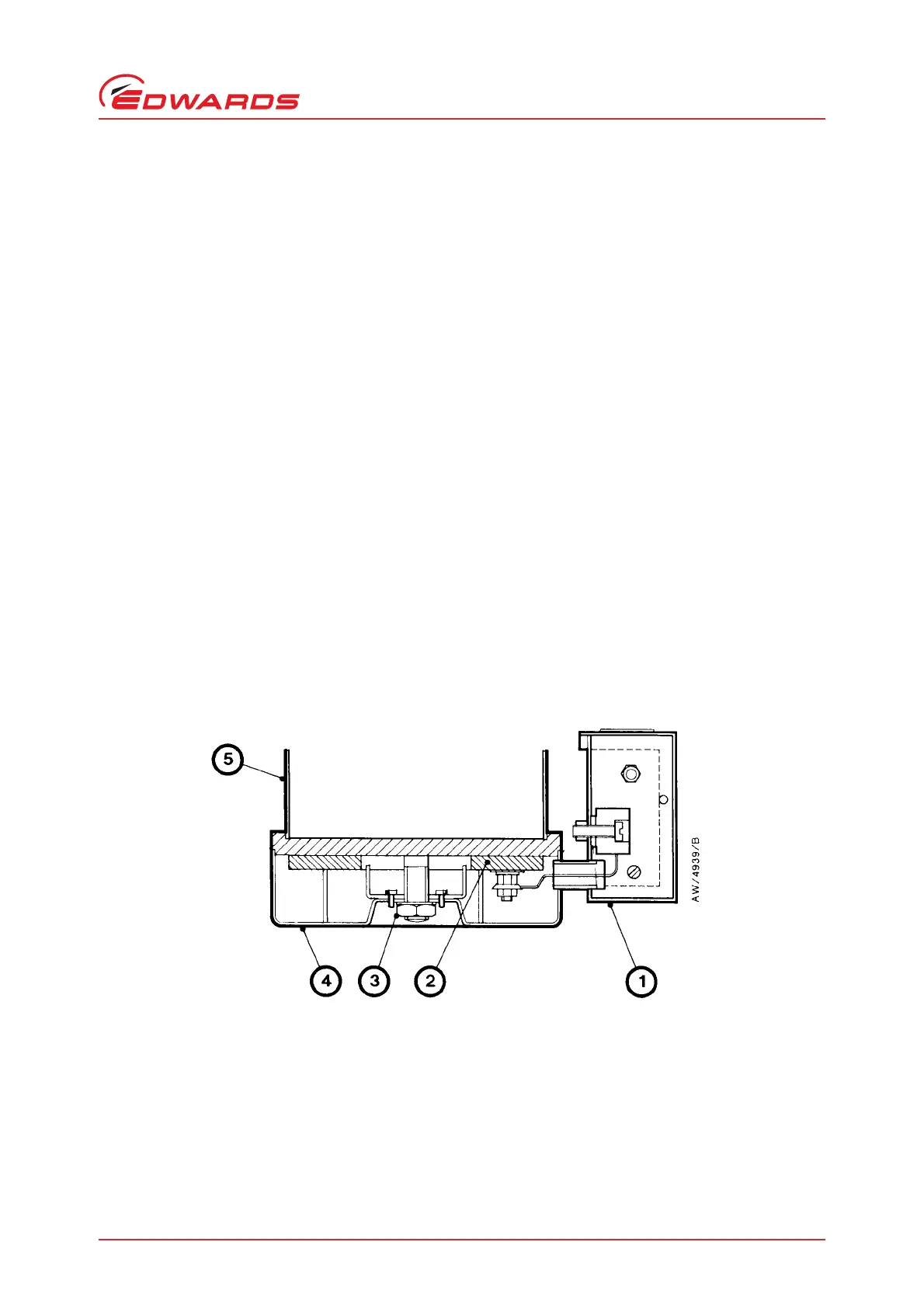
Figure 26 - Heater assembly: Diffstak 160/700 and 250/2000 pumps
1. Terminal-box
2. Heater
3. Nut
4. Nut
5. Radiation shield
6. Clamp plates
7. Pump boiler