© Edwards Limited 2011. All rights reserved. Page 63
Edwards and the Edwards logo are trademarks of Edwards Limited.
Maintenance
A705-40-880 Issue B
12.If the gap is not correct:
Check that the bottom flange of the coupling cover (12) is correctly located against the top flange of the
pump-motor: refer to Section 5.15.7.
Check that the top flange of the coupling cover (12) is correctly located against the bottom flange of the
pump gearbox (1): refer to Step 1 to 10 and to the WARNING at the start of this section.
Check that the torque limiter or coupling hub (5) is located on the motor shaft (6 or 7).
If the coupling cover and the torque limiter or drive hub are correctly fitted, loosen the two grub-screws (14)
on the coupling (15) and adjust the position of the coupling, then tighten the two grub-screws (14) again.
Continue at Step 11 to check the gap is now set correctly.
13.Refer to Figure 16. Undo and remove the three nuts and washers (5) from the studs (3) and remove the motor
change frame (6) from the studs. Undo and remove the three nuts and washers (2) and remove the three studs
(3) from the pump frame (4).
14.Fit the remaining two M16 fixing bolts (8) to fully secure the coupling cover and pump-motor assembly to the
pump.
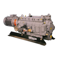
5.16 Fit a replacement service module
5.16.1 Introduction
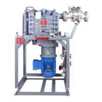
A service module is a basic pump body without the following components fitted: pump motor, coupling cover,
coupling hub, torque limiter (if applicable), inlet adaptor, coolant jacket thermal snap-switch (if applicable),
exhaust manifold and pressure relief valve.
To fit a replacement service module to your pump, you must:
Disconnect your pump from your process and exhaust systems.
Remove the items listed above from your pump service module, then remove the service module from your
pump frame.
Fit the new (replacement) service module to your pump frame. Inspect the O-ring sealing surface on the
inlet adaptor, on the exhaust manifold and the pressure relief valve for damage and scratches. Then fit the
items removed from your old pump to the new service module.
Reconnect the pump to the process and exhaust systems.
Leak test the pump.
Use the procedures in Section 5.16.2 to 5.16.5 to replace a service module.
Note: You must only use the following procedures if you are satisfied that you have the necessary tools and skills
required to correctly replace the service module. If you have any doubts, you must contact Edwards or your
supplier for advice.
If your pump is part of an ATEX system, you must leak test the pump after re-fitting all components
to the pump. If you fail to do so, the ATEX certification of your system will be invalid.
 Loading...


