© Edwards Limited 2008. All rights reserved. Page 3
Edwards and the Edwards logo are trade marks of Edwards Limited.
Introduction
A546–00–880 Issue C
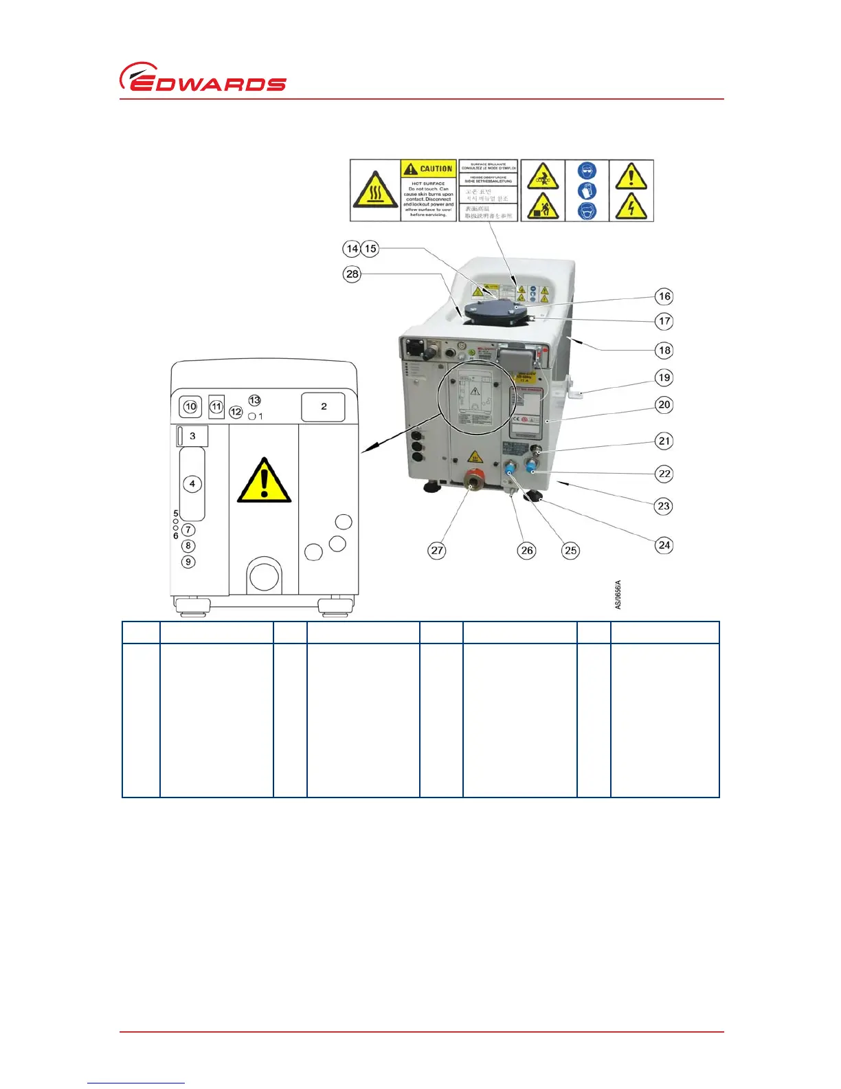
Figure 2 - The controls/connectors
Item
Control/connector
identification
Item
Control/connector
identification
Item
Control/connector
identification
Item
Control/connector
identification
1Protective earth (ground)
M5
8Comms 2 - LON module
connection
15 Lifting eyebolt 22 Cooling-water supply
connection
2Electrical supply
connection
9Comms 1 - System control/
PDT 2 connection
16 Pumped gas inlet
connection
23 Castors (3 off)
3Rear status panel10Gate valve interface (EMO
on T variant)
17 RF earth (ground) cable 24 Levelling feet (4 off)
4 Comms 4 - MicroTIM
connection (if fitted)
11 EMS* 18 Interstage connection (if
fitted)
25 Cooling-water return
connection
5 Ethernet active LED 12 Accessory module
interface
*
*
not on T variants
19 Seismic bracket (if fitted, 4
off)
26 RF earth (ground) stud M6
6Ethernet installed LED 13 GRC interface* 20Gas Module access panel 27 Exhaust gas outlet
connection
7Comms 3 Ethernet
connection
14 Extraction port 21 Nitrogen purge port 28 Leak-test port
 Loading...