A546–00–880 Issue C
Page 12 © Edwards Limited 2008. All rights reserved.
Edwards and the Edwards logo are trade marks of Edwards Limited.
Installation
3.1 Locate the dry pumping system
Use the following procedure to locate the iGX system in its operating position. The iGX system must be located on a
firm, level surface, to ensure that the system is not damaged.
1. Use suitable lifting equipment (refer to Figure 2) attached to the lifting eyebolt (15) to move the iGX system
close to its final operating position.
2. Adjust the levelling feet (24) to make sure that the iGX system is level and is not supported by the castors. The
lifting eyebolt must be retained for future use with this system.
3. If required, the iGX system can be secured to the floor by fitting suitable bolts or studs (not supplied) through
the M10 docking points on the chassis.
If vibration transmission to the floor is a concern, suitable vibration isolators (not supplied) should be fitted
between the docking points and the bolt or stud, if doing this the levelling feet will need to be removed.
4. If preferred, the lifting eyebolt can be removed and replaced with the lifting eyebolt hole plug supplied with the
systems.
5. Ensure that access is possible to the emergency stop button (refer to Figure 4, item 1), if not use an iGX
Disconnect Box (refer to Section 7.3).
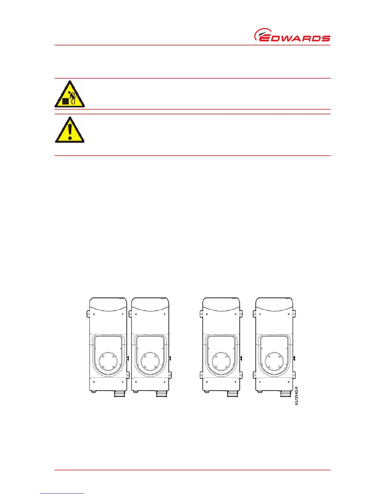
Figure 7 - System arrangment to reduce effective footprint (if required)
If you want to secure the iGX in place to prevent inadvertent movement (for example, during an earthquake), take
note of the following:
z The iGX system seismic brackets (Figure 2, item 19) are designed to withstand a level 4 earthquake in a
ground floor installation.
 Loading...