© Edwards Limited 2008. All rights reserved. Page 17
Edwards and the Edwards logo are trade marks of Edwards Limited.
Installation
A546–00–880 Issue C
Remote:
1. Attach the strain relief bush to the cover. Then pass a suitable cable through the strain relief bush and cover.
The cross-sectional area of the cable wires should be 6 mm
2
. Phase wires must be bare ended without ferrules to
ensure correct clamping in the connector block.
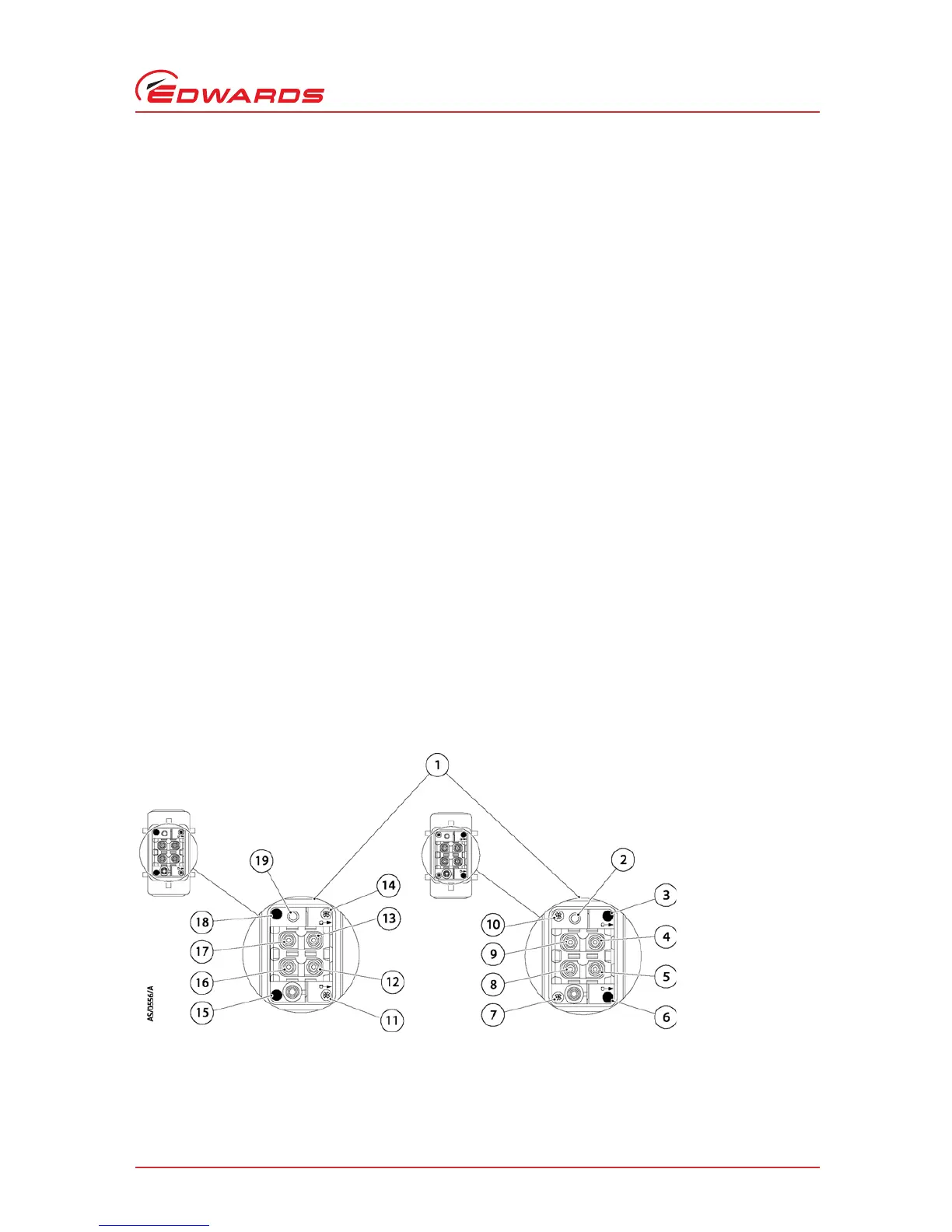
2. Fit the coding pins to the connector block according to the voltage variant as shown in Figure 8 ’High and low
volt coding pin arrangement’.
3. Connect the cable phase wires to the following connections on the connector block. Refer to Figure 9.
z R/L1 to a1
z S/L2 to a2
z T/L3 to b1
z Prepare the end of the 6 mm
2
wire as shown in Figure 9. Do not twist the wire further.
z Insert the wire into the appropriate contact chamber.
Tighten the connection using a 2 mm allen key as shown in Figure 9 to a torque of 1 Nm. During tightening firmly
hold the wire in position.
4. Connect the earth (ground) wire of the cable to one of the two earth (ground) connections on the connector
block using the following procedure:
z Prepare the end of the 6 mm
2
wire to a strip length of 10 mm. Twist strands or fit a ferrule.
z Insert the wire into the earth terminal block.
z Tighten the connection using a flat blade screwdriver.
5. Refit the cover to the connector block, then tighten the strain relief bush.
6. Connect the mating half to the electrical supply connector of the iGX system (Figure 2, item 2).
Connect the other end of the electrical supply cable to your electrical supply through a suitable isolator.
Figure 8 - High and low volt coding pin arrangement
 Loading...