© Edwards Limited 2008. All rights reserved. Page 21
Edwards and the Edwards logo are trade marks of Edwards Limited.
Installation
A546–00–880 Issue C
7. If your iGX system is an L or M variant, continue at step 8.
For N variants, the nitrogen purge flow should be checked as follows;
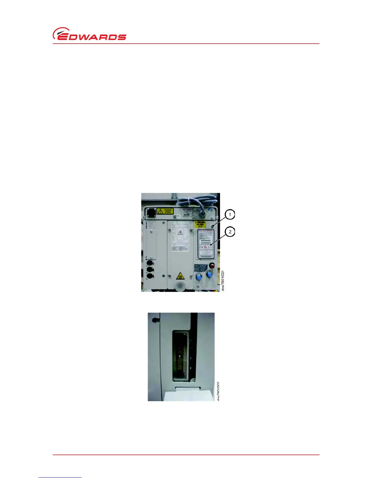
i. Open the gas module access panel by removing the securing screw. Refer to Figure 12 for the iGX100, (same
location for iGX600).
ii. Confirm the flow is 14 slm (factory default setting). The centre of the ball should be aligned to the 14 slm
marking on the flow tube (refer to Figure 13).
If not, then proceed at step (iii);
iii. Close (clockwise) the 4/5 variable restrictor (marked 4/5) and confirm the flow rate is 4 slm. If not, then
adjust the shaft seals variable restrictor (marked SS) until the flow tube indicates a flow rate of 4 slm (refer
to Figure 14).
iv. Open (anti-clockwise) the 4/5 variable restrictor until the flow tube indicates a total flow of 14 slm (refer to
Figure 13).
v. Re p l a c e t h e g a s m od ul e ac ce ss p an el .
Figure 12 - Gas module access panel
Figure 13 - Flow tube (14 slm)
 Loading...