D374-20-880 Issue E
Page 18 © Edwards Limited 2007. All rights reserved.
Edwards and the Edwards logo are trademarks of Edwards Limited.
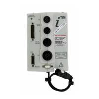
Serial Interface Operation
In Table 8, items enclosed in curled brackets (e.g. {parameter}), are items that you must specify or are variable
items. These items are Table 6.
Refer to {bitfield status} (see Table 10) to determine the cause of the alarm.
Table 6 - Variable items
{alarm type} This specifies the type of an alarm. Refer to Table 7.
{bitfield status} This is a number in the range 0 to 65535. When interpreted as a binary number, the
bits set specify the error status of a parameter. Refer to Table 11.
{booster pump} This is a digit that specifies the mechanical booster pump in the system: 1 = no
booster pump fitted, 2 = iQMB250/500, 3 = iQMB1200, 4 = QMBDD, 5 = HCMB600,
6=HCMB1000.
{control object} This can take any value between 0 and 255 and specifies the part of the system that
has control of the dry pumping system. Refer to Table 13 for typical values.
{dry pump} This is a digit that specifies the dry pump in the system: 1 = invalid DIP switch
setting, 2 = iQDP40, 3 = iQDP80, 4 = iH80 and 5 = iL70.
{node type} This is a number that represents the pump node type (extracted from the node
broadcast): 1 = iQ, 22 = iH and 41 = iL.
{number} The number of parameters that have a priority level > 0. Refer to Table 10.
{on/off} This specifies the status of a parameter and can be 0 or 1. Refer to Section 5.3.2 to
5.3.13.
{on process status} This can be 1 or 0 and specifies whether the On process flag is set (1) or not set (0).
{parameter} This specifies a selected parameter. Refer to Table 9.
{priority level} This specifies the priority level of a parameter. Refer to Table 10.
{run til crash status} This can be 0 or 1 and specifies whether run til crash is selected (1) or not selected
(0).
{serial number} This is a 16 character string that specifies the serial number of the dry pumping
system.
{status level} This specifies the status level of a parameter. Refer to Table 12.
{system type} This is a number that indicates the type of the dry pumping system: 0 indicates iQ, 1
indicates iH and 2 indicates iL.
{u} This field is currently unused by the dry pumping system, but is included for possible
future use.
{value} This specifies the current value of a parameter. Refer to Table 9 for the parameters
and the units used for each parameter.
Table 7 - Alarm type
Value Meaning
0No alarm
1 Digital alarm
9Low warning
10 Low alarm
11 High warning
12 High alarm
13 Device error*
14 Device not present