© Edwards Limited 2015. All rights reserved. Page 3
Edwards and the Edwards logo are trademarks of Edwards Limited.
Introduction
A540-55-880 Issue D
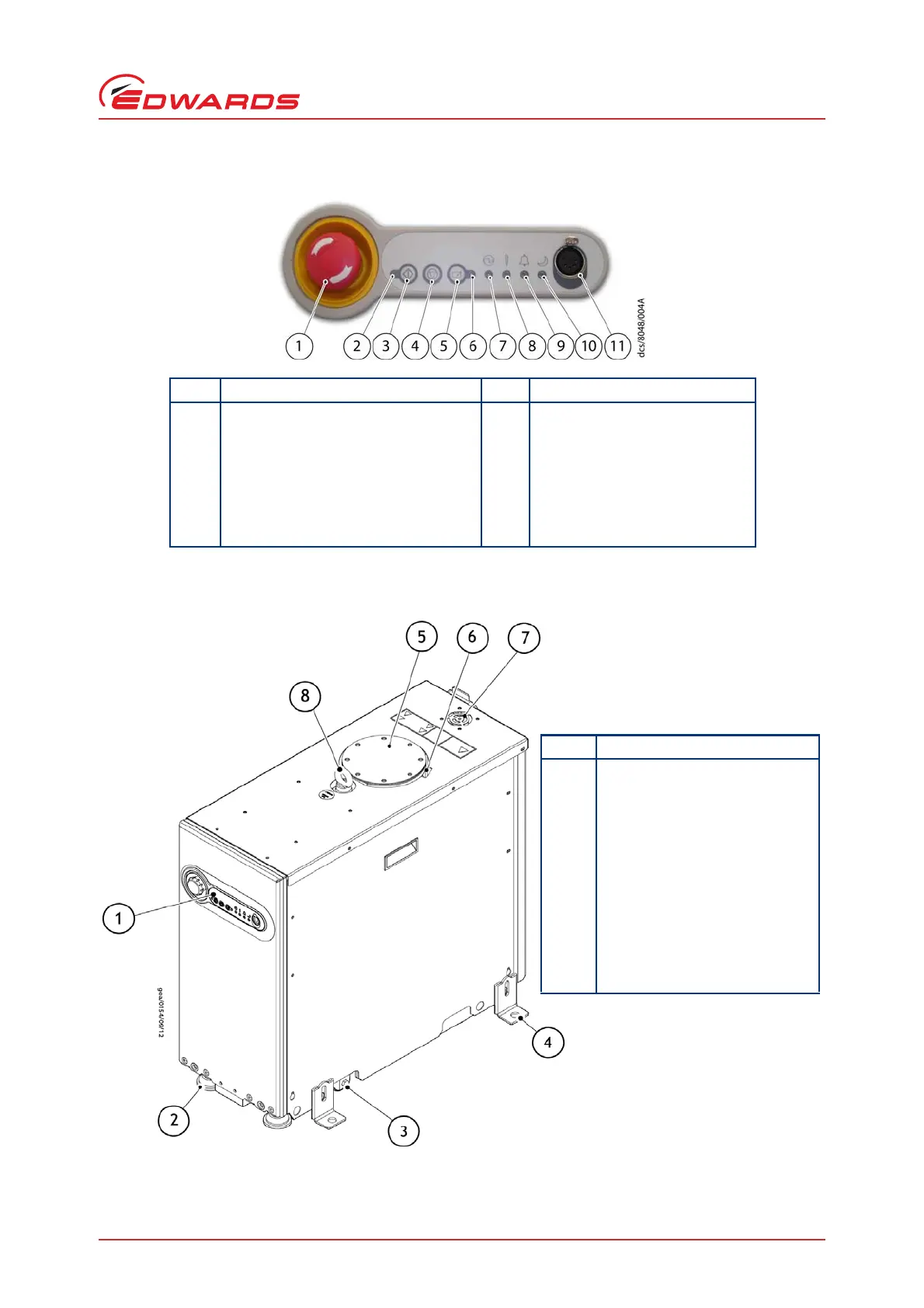
Figure 2 - The front panel controls
Figure 3 - Front view of pumping system
Item Control/connector identification Item Control/connector identification
1 EMS button 7 Power LED (green)
2 Running LED (green) 8 Warning LED (amber)
3 Start button 9 Alarm LED (red)
4 Stop button 10 Green Mode LED (green)
5 Local control button 11 PDT (Pump Display Terminal)
6 Local control LED (green) connection
Item Control/connector identification
1 Front panel control
2 Levelling feet (4 off)
3 Castors (4 off)
4 Seismic bracket (4 off if fitted)
Note: Diagram shows side
fitting location
5 Pumped gas inlet connection
6 RF Earth (ground) cable
7 Extraction port
8 Lifting eyebolt (1 off)