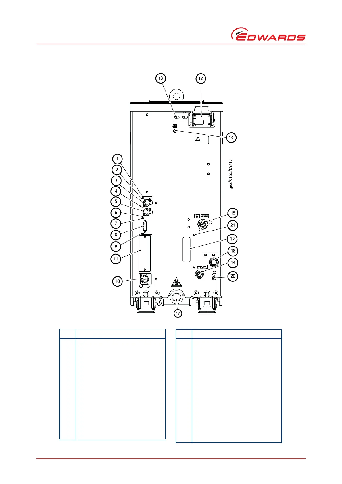
Item Control/connector identification
1 Ethernet LAN LED (green)
2 Ethernet link LED (yellow)
3 Ethernet connection
4 Power LED (green)
5System interface
6 Warning LED (yellow)
7 Running and Alarm LED (changes
colour according to system status,
either green or red)
8 Accessory interface
9 MicroTIM in control LED (green)
10 EMS interface
11 Micro TIM connection (if fitted)
12 Electrical supply connection
13 Electrical connector locking
mechanism
14 Nitrogen purge connection (if fitted)
15 Cooling water supply connection
16 Protective earth (ground) M5 stud
17 Exhaust gas outlet connection
18 Cooling water return connection
19 Nitrogen Purge Flow Meter (if fitted)
20 RF Earth M6 stud (ground)
21 Nitrogen purge adjustment (if fitted)
Item Control/connector identification