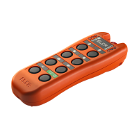
ENG man MAGO-EVO 03 MAGO-EVO Radio Remote Control
- Page 15 -
ENGLISH
7.1 ATTENTION
The instructions laid out here must be effected by quali ed personnel and strictly during maintenance and for
the replacement of existing faulty transmitter, with the machine in a stand still safe condition.
This procedure allows you to couple a new transmitter to an existing receiver in a univocal manner with reference to the
norms IEC 60204-1 and IEC60204-32 which states that only one transmitter at a time can control a machine. At the end
of this procedure the original transmitter connected to the receiver will no longer be valid and only the new transmitter will
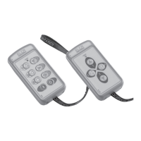
be able to control the machine, substituting the previous transmitter.
At the end of the procedure the new transmitter will have the original programmable functions as set by the manufacturer,
which by default are:
a) START UP SEQUENCE: Start - G - Start
b) AUTOSHUTOFF: 5 minutes.
In the event the factory settings were modi ed, you will be required to make the changes again as indicated in the manual
section 2.4.
Upon completion of the coupling procedure always verify that the new transmitter is working correctly, that all the
commands are working, in particular the STOP command
IMPORTANT : the data label on the original transmitter should be removed and applied to the new transmitter. If this is not
possible because it has been lost, destroyed, or illegible, please contact an ELCA Service Center to request a duplicate.
On the same receiving unit can be replaced up to a maximum of 15 different transmitting units.
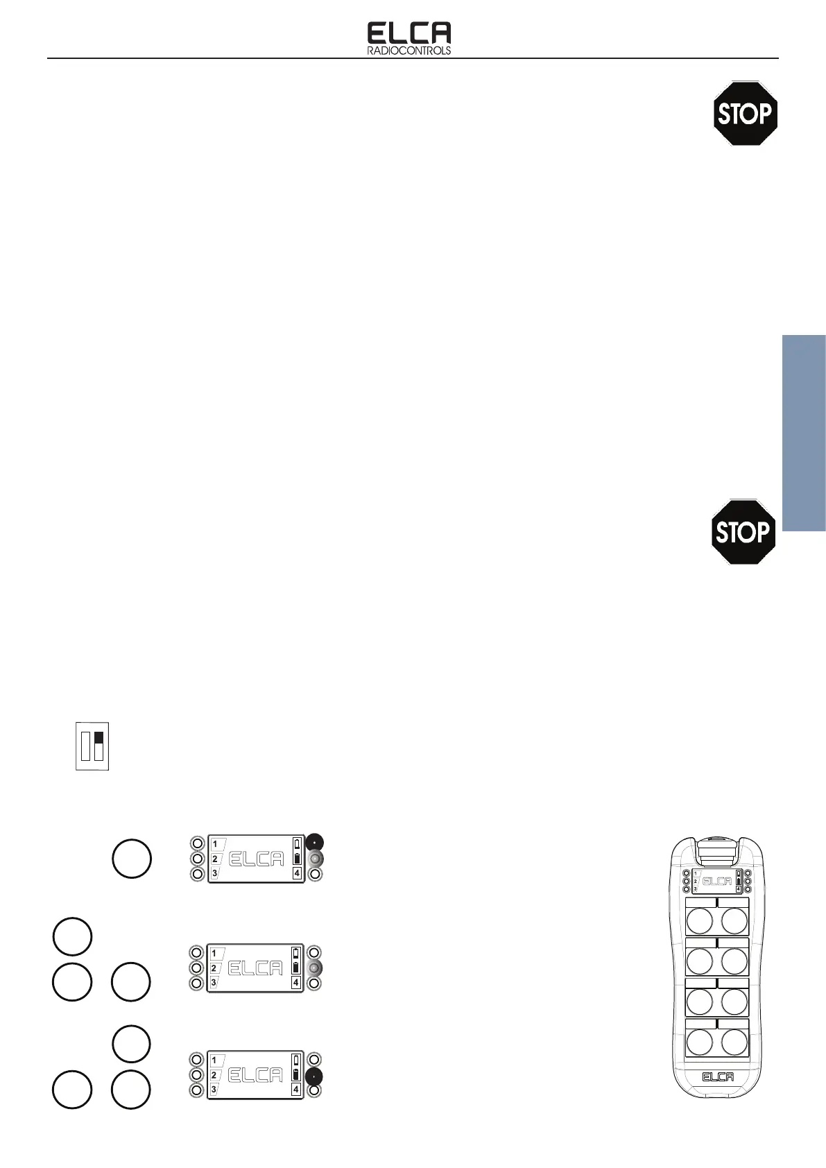
7. TRANSMITTING UNIT REPLACEMENT
At rst verify that the new transmitter does not contain stored coupling data: to do this press the START button with the
mushroom stop released which should result in a xed red LED and a ashing green one. In the event this does not
occur you will need to effect an ERASING procedure (paragraph 7.2) which will cancel any stored data.
Now make sure the new transmitter is OFF, with Mushroom stop released.
1. Unplug power supply from receiving unit.
2. Open the cover of the receiving unit and set the dip-switch on motherboard with position 2 to ON. Refer to the
gure on page 12 paragraph 5.1 to identify the position of the DIP switch.
3. Connect power supply to receiving unit. POWER LED turns on.
4. Within two minutes execute as described below:
7.2 COUPLING PROCEDURE
START
Press and hold the START button until Red
LED lights up and the Green LED ashes.
If this does not happen you must effect the
ERASING procedure (see par.7.4).
Simultaneously press together G, START
e B buttons until Green LED lights up. Now
coupling data are stored.
START
Simultaneously press together G, START e
A buttons until Red LED turns off and Green
LED ashes. On the receiver ENABLE LED
lights up.
START
1 2
ON