05/2019 - Art. Nr. 4200 1043 1803F40
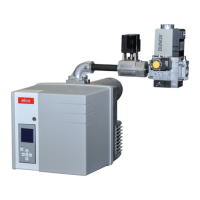
Gas train components
Gas pressure switch
Technical data:
Type of gas:
Gases according to DVGW Worksheet
G 260/1, gas families 1, 2, 3
Protection level: IP 54
Ambient temp.: -15°C to +50°C
Installation position: any
Operating pressure up to:
GW 50/150 A5A6500 mbar
GW 500/ A5/A6 600 mbar
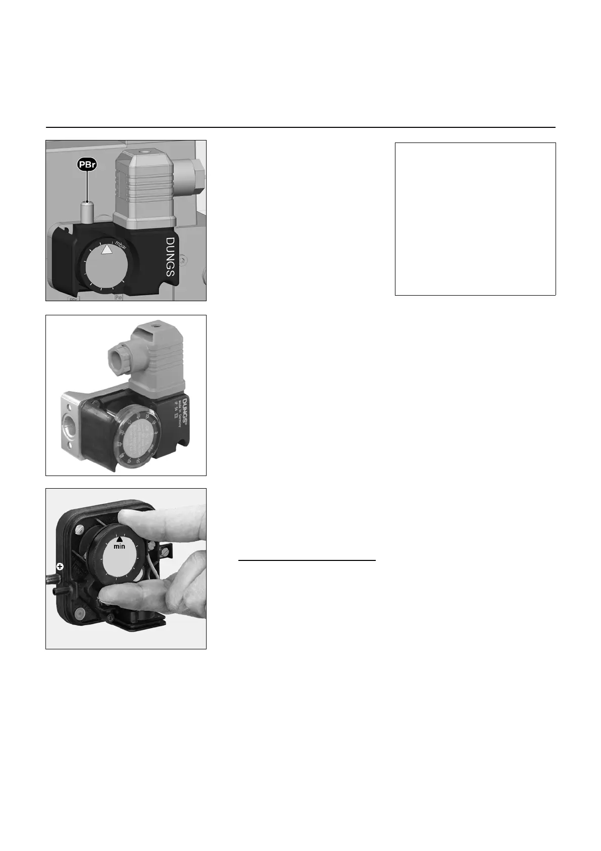
Gas pressure switch GW...A5/A6
The gas pressure switch is designed to
monitor the gas flow pressure. It can be
used for monitoring either falling
pressure (minimum) or rising pressure
(maximum, specified for equipment
according to TRD 604).
The types GW...A5/A6 may be used as
pressure switches of a specific
construction according to VdTÜV leaflet
"Pressure 100/1" for application in
furnaces complying with TRD 604.
The setpoint (switching point) is
adjusted using a setting wheel with
scale.
Certification
The pressure switch has been tested in
accordance with EN1854 and is CE/
DIN-DVGW-registered. It has been
registered in other important gas
consumption countries.
N.B.(Gas and air pressure switches)
The pressure switches must be set in
accordance with the specifications.
Furthermore, each time they are set, a
function test must be carried out.
Non-compliance could result in
personal injury or damage to
property!
Once the pressure switches have
been set, they must be protected to
prevent settings from being altered.
For example, this can be done by
placing a spot of varnish on at least
one of the screws on the equipment's
protective cover.
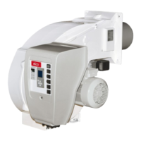
Setting the min. gas pressure switch
Remove the protective cover. At the
rated output, measure the gas flow
pressure and calculate the switch-off
pressure by reducing by approximately
20%. Adjust the graduated disc to the
desired switch-off pressure opposite the
arrow (the graduations are approximate
values). Operate the burner at minimum
power. Close the gas cut-off valve slowly
to obtain the desired switch-off pressure.
Turn the graduated disc until the burner
switches off. Refit and screw down the
protective cover.
Max. gas pressure switch
Remove the protective cover. At the
rated output, measure the gas flow
pressure and calculate the switch-off
pressure by increasing by approximately
20% (no more than 30% under any
circumstances). Adjust the graduated
disc to the desired switch-off pressure
opposite the arrow (the graduations are
approximate values). Operate the
burner at minimum power. If the max.
gas pressure switch switches off the
burner, increase the adjustment value
but not to more than 130% of the flow
pressure at the rated output.
 Loading...