05/2019 - Art. Nr. 4200 1043 1803F56
The list contains the minimum number of switching cycles and the shortest possible service life for wear parts* and safety-related
components. The actual service life could be much higher and this depends on the operating conditions. For reasons of operational and
functional safety, the recommended periods of use should not be exceeded.
* Wear parts in the case of 25 years of machine usage
Safety-related components
Recom. useful
service life
Min. operating cycles
Valve testing systems
10 years 250 000
Gas and air pressure switches
10 years -
Automatic firing device with flame monitor for the burner
10 years 250 000
Flame monitor (UV cells)
10,000 hours of operation
Flame monitor (not UV cells)
10 years 250 000
Gas pressure regulator
15 years -
Gas valve with valve testing system
after a fault is detected
Gas valve without valve testing system
10 years 250 000
Pressure relief valve
10 years -
Fuel-air ratio control
10 years -
Servomotor STE…(Schneider Electric)
10 years 2 000 000
Servomotor SQM 1../2.. (Siemens)
Depends on usage 150 000
Servomotor SQM 5... (Siemens)
Depends on usage 250 000
Servomotor 6 / 16 Nm (Lamtec)
10 years 500 000
Servomotor STM 30/40 (Schneider Electric)
10 years 500 000
Servomotor 01-15/30 Schimpf
10 years 2 000 000
Oil hoses
5 years -
Fuel-oil valves
10 years 250 000
Pressure relief valve
10 years -
Useful service life of wear parts *
Auxiliary relay
Depends on usage 50 000
Cooling fan frequency converter (ACS310)
3 years 25,000 hours of operation
Cooling fan frequency converter (ACH550, ACH580)
6 years 60,000 hours of operation
Motor
40,000 hours of operation
Servicing
Maintenance
Replacing the control unit
Warning!
Replace any damaged or defective com-
ponents! Replace safety components
before their end of life! Never operate
the burner with damaged or defective
parts. Using defective or damaged com-
ponents may cause malfunctioning and
hazardous operation. This may result in
a switch to malfunction mode or damage
to the environment and to the installa-
tion, and may even cause injury (risks of
serious or fatal injury).
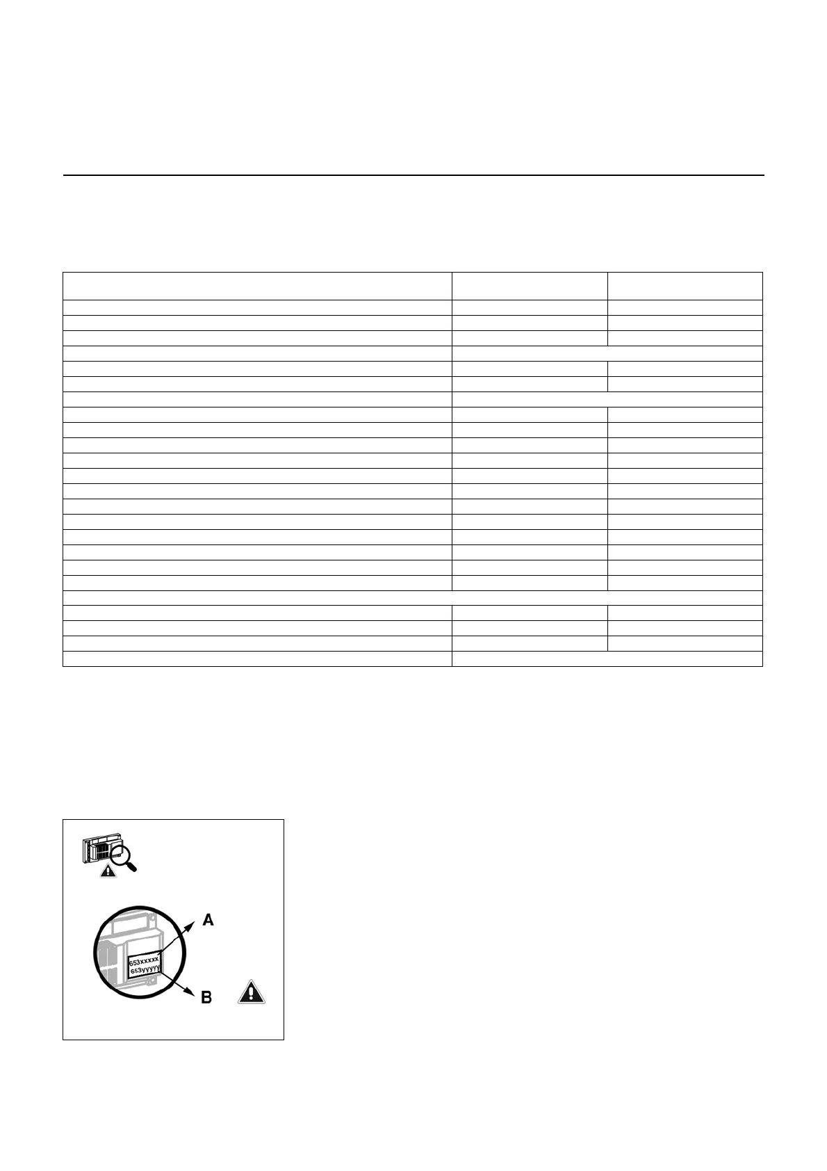
Note for replacing the control unit
(Burnertronic):
Two different spare parts can be
installed in order to replace the control
unit! Please see the order reference on
the label:
• Select the item code for the spare part
in accordance with the marking
displayed on unit BT3xx:
- A: Standard settings, without specific
parameter configuration: specific
burner configuration must be
performed on the system
(commissioning can only be carried
out using the PC-Remote Software
tool)
- B: unit programmed in the factory, with
parameter configuration specific to the
burner or to the customer (factory
setting). To order this code, the
following information must be made
available: the item code, the order
code, the manufacturing serial
number (see rating plate). If no
changes have been made to the
burner, recommissioning can be
carried out via the display (except for
burners equipped with O2 and CO
regulation and a Profibus, in which
case the PC-Remote Software must
be used)
Attention! if a single item code is shown
on the unit label, this means it is a BT3xx
fully preconfigured according to variant
B, nevertheless when ordering the spare
part it is not necessary to provide the
item code, order code and
manufacturing serial number. As for
variant B: if no changes have been
made to the burner, recommissioning
can be carried out via the display
(except for burners equipped with O2/
and CO regulation and a Profibus, in
which case the PC-Remote Software
must be used)
Note
When replacing the Burnertronic BT
XXX it is recommended to save the data
before disassembling the appliance. To
this end backup all the date. The
relevant procedure is described in the
operating instructions "BurnerTronic
BT300 - Remote Software,
Maintenance" (Art. No. 4200 1017 53xx)
under chapters "Files" and "Data
Saving". This will allow the burner to
restart easily and quickly after replacing
the Burnertronic.
 Loading...