05/2019 - Art. Nr. 4200 1043 1803F 7
Installation
General information regarding burner installation
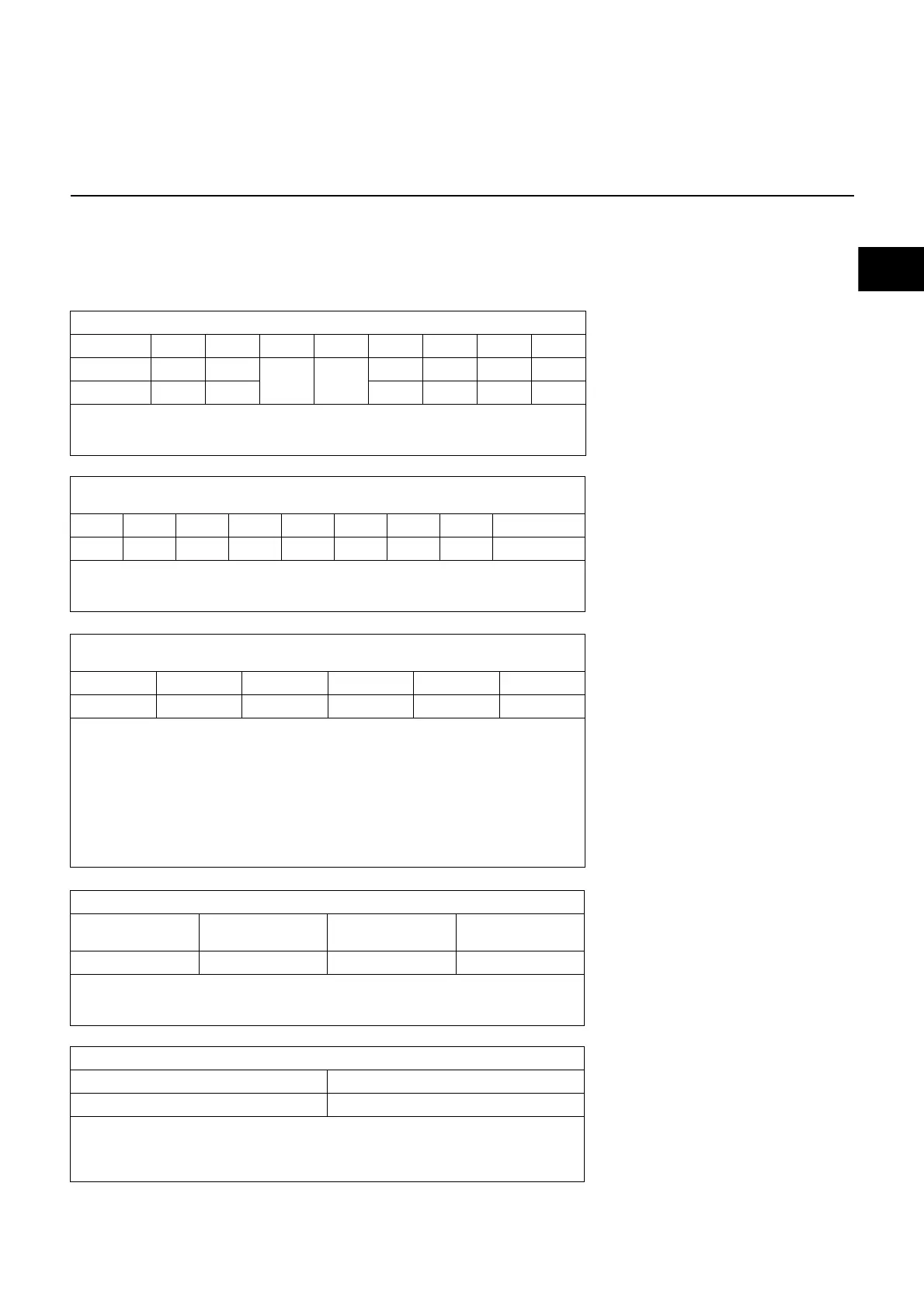
Tightening torques
During installation, commissioning and
maintenance, the following torques for
screw connections must be observed.
Recommended tightening torques
Standard unions
M4 M5 M6 M8 M10 M12 M16 M20
2 6 10 25 48 85 210 415 Nm
N.B.:
In general, the correct tightening torques have been applied when the unions are
tightened hand-tight using a screwdriver (ISO 272) or angled Allen key.
Tightening torques for root connector for fan impeller
SM16 (Ø28)
No.: 1615
SM20 (Ø38 and 42)
No.: 2012
SM25 (Ø42 and 48)
No.: 2517
Bushing
20 30 50 Nm
N.B.:
For more information regarding installation/dismantling of the fan impeller, please
refer to the relevant chapter in the operating instructions.
Tightening torques flange connection solenoid valves and gas filter
M16 / DN 65 - DN 125 M20 / DN 150
max. 50 Nm max. 90 Nm
N.B.:
The unions must be tightened crosswise. The union must be checked to ensure it
is tight. If it is not sufficiently tight, the valve must be removed and checked
(tightening surfaces).
Max. tightening torques for accessories system, double gas valve
M4 M5 M6 M8 G1/8 G1/4 G1/2 G3/4
Siemens 3 Nm -
7 Nm 15 Nm
8 Nm 15 Nm - 35 Nm
Dungs 2,5 Nm 5 Nm 5 Nm 7 Nm 10 Nm 15 Nm
N.B.:
In general, the correct tightening torques have been applied when the unions are
tightened hand-tight using a screwdriver (ISO 272) or angled Allen key.
Tightening torques of electrical connections
for bolts on terminal boards
M4 M5 M6 M8 M10
1.2 2 3 6 10 Nm
Note:
Check the tightness of electrical connections before using the burner. Make sure to
observe the tightening torques listed above!
WARNING:
Electrical shock hazard!
There is a risk of coming into contact with live parts! This could lead to fatal electrical
shock!
The motor must be switched off via an omnipolar cut-off switch and protected
against accidental reconnection.
 Loading...